Subaru Crosstrek Service Manual: How to read wiring diagrams
WIRING SYSTEM > Basic Diagnostic Procedure
HOW TO READ WIRING DIAGRAMS
1. WIRING DIAGRAM
The wiring diagram of each system is illustrated so that you can understand the path through which the electric current flows from the battery.
Sketches and codes are used in the diagrams. They should read as follows:
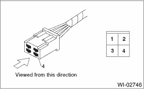
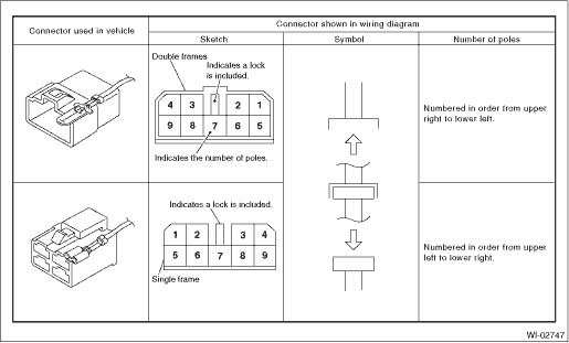
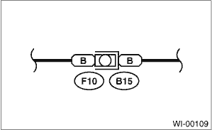
• Each connector and its terminal position are indicated by a sketch of the connector in a disconnected state which is viewed from the front.
• The number of poles or pins, presence of a lock are indicated in the sketch of each connector. In the sketch, the highest pole number refers to the number of poles which the connector has. For example, the sketch of the connector shown in figure indicates the connector has 9 poles.
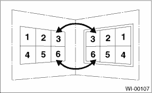
• When one set of connectors is viewed from the front side, the pole numbers of one connector are symmetrical to those of the other. When these two connectors are connected as a unit, the poles which have the same number are joined.
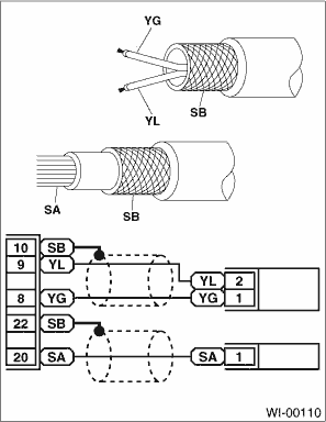
• Wiring diagram:
The connectors are numbered along with the number of poles, external colors, and mating connections in the accompanying list.
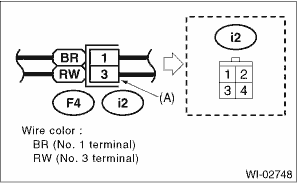
• The sketch of each connector in the wiring diagram usually shows the (A) side of the connector. The relationship between the wire color, terminal number and connector is described in the figure.
NOTE:
A wire which runs in one direction from a connector terminal sometimes may have a different color from that which runs in the other direction from that terminal.
• In the wiring diagram, connectors which have no terminal number refer to one-pole types. Sketches of these connectors are omitted intentionally.
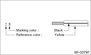
• The following color codes are used to indicate the colors of the wires.
Color code | Color |
L | Blue |
B | Black |
Y | Yellow |
G | Green |
R | Red |
W | White |
Br | Brown |
Lg | Light green |
Gr | Gray |
P | Pink |
Or | Orange |
Sb | Light blue |
V | Violet |
SA | Sealed (inner) |
SB | Sealed (outer) |
• The wire color code, which consists of two letters (or three letters including Br or Lg), indicates the standard color (base color of the wire covering) by its first letter and the stripe marking by its second letter.
• The table lists the nominal sectional areas and allowable currents of the wires.
CAUTION:
When replacing or repairing a wire, be sure to use the same size and type of the wire which was originally used.
NOTE:
• The allowable current in the table indicates the tolerable amperage of each wire at an ambient temperature of 40°C (104°F).
• The allowable current changes with ambient temperature. Also, it changes if a bundle of more than two wires is used.
Nominal sectional area | No. of strands/strand diameter | Outside diameter of wiring | Allowable current Amps/ 40°C (104°F) |
mm2 | mm | ||
0.3 | 7/0.26 | 1.8 | 7 |
0.5 | 7/0.32 | 2.2 (or 2.0) | 12 |
0.75 | 30/0.18 | 2.6 (or 2.4) | 16 |
0.85 | 11/0.32 | 2.4 (or 2.2) | 16 |
1.25 | 16/0.32 | 2.7 (or 2.5) | 21 |
2 | 26/0.32 | 3.1 (or 2.9) | 28 |
3 | 41/0.32 | 3.8 (or 3.6) | 38 |
5 | 65/0.32 | 4.6 (or 4.4) | 51 |
8 | 50/0.45 | 5.5 | 67 |
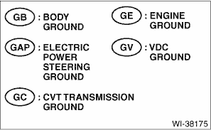
• Each unit is either directly grounded to the body or indirectly grounds through a harness ground terminal. Different symbols are used in the wiring diagram to identify the two grounding systems.
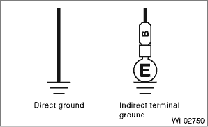
• The ground points shown in the wiring diagram refer to the following:
NOTE:
All wiring harnesses are provided with a ground point which must be securely connected.
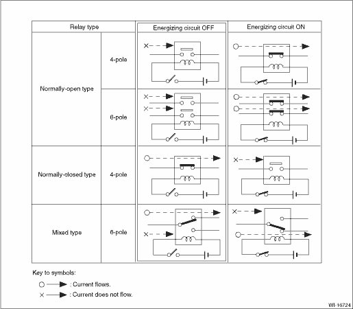
• Relays are classified as normally-open or normally-closed.
The normally-closed relay has one or more contacts. The wiring diagram shows the relay mode when the energizing circuit is OFF.
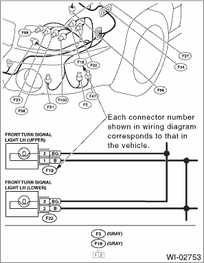
• Each connector number shown in the wiring diagram corresponds to that in the wiring harness. The location of each connector in the actual vehicle is determined by reading the first character of the connector (for example, a “F” for F8, “i” for i16, etc.) and the type of wiring harness. The first character of each connector number corresponds to the area or system of the vehicle.
Symbol | Wiring harness and cord |
F | Front wiring harness |
B | Bulkhead wiring harness |
E | Engine wiring harness |
T | Transmission cord |
D | Door cord LH & RH, Rear gate cord Rear door cord LH & RH, Rear defogger cord |
i | Instrument panel wiring harness |
R | Rear wiring harness, Fuel tank cord, Roof cord, Rear gate cord |
AB | Airbag wiring harness |
 Basic inspection
WIRING SYSTEM > Basic Diagnostic ProcedureBASIC INSPECTION1. VOLTAGE MEASUREMENT1. Using a voltmeter, connect the negative lead to a good ground point or negative battery terminal and the positive ...
 Symbols in wiring diagrams
WIRING SYSTEM > Basic Diagnostic ProcedureSYMBOLS IN WIRING DIAGRAMSA number of symbols are used in each wiring diagram to easily identify parts or circuits.1. RELAYA symbol used to indicate a rela ...
Other materials:
Dtc u0423 invalid data received from instrument panel cluster control module
HVAC SYSTEM (AUTO A/C) (DIAGNOSTICS) > Diagnostic Procedure with Diagnostic Trouble Code (DTC)DTC U0423 INVALID DATA RECEIVED FROM INSTRUMENT PANEL CLUSTER CONTROL MODULEThis is detected when CAN data from meter is abnormal.NOTE:Perform the diagnosis for LAN system. Basic Diagnostic Procedure &g ...
Note
VEHICLE DYNAMICS CONTROL (VDC) > Vehicle Dynamics Control SystemNOTEFor operation procedures of each component of the vehicle dynamics control system, refer to the respective section.• VDC control module & hydraulic control unit (VDCCM&H/U): VDC Control Module and Hydraulic Control ...
Installation
SECURITY AND LOCKS > Keyless Access CMINSTALLATIONCAUTION:• When the control module related to immobilizer has been replaced, be sure to perform the registration of immobilizer system. For detailed operation procedure, refer to “Type D” described in “REGISTRATION MANUAL FO ...
