Subaru Crosstrek Service Manual: Front wiring harness Location
WIRING SYSTEM > Front Wiring Harness
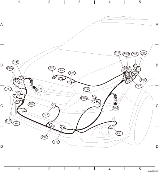
LOCATION
Connector | Connecting to | ||||
No. | Pole | Color | Area | No. | Description |
F5 | 1 | Black | C-1 | Horn | |
F6 | 2 |
| C-1 | Front fog light RH (without SRF) | |
2 | Black | C-1 | Front fog light RH (with SRF) | ||
F16 | 2 |
| C-1 | Sub fan motor | |
F17 | 2 |
| D-2 | Main fan motor | |
F21 | 2 |
| D-4 | Front fog light LH (without SRF) | |
2 | Black | D-4 | Front fog light LH (with SRF) | ||
F24 | 1 |
| B-3 | Magnet clutch | |
F25 | 1 |
| B-2 | Generator terminal B | |
F26 | 3 |
| B-2 | Generator | |
F27 | 26 |
| B-5 | Relay holder | |
F35 | 12 | Blue | B-5 | M/B | |
F36 | 7 |
| B-5 | ||
F37 | 20 |
| B-5 | ||
F47 | 1 | Black | C-2 | Horn | |
F78 | 2 | Black | C-2 | Ambient sensor | |
F103 | 2 | Gray | C-1 | Daytime running light resistor | |
F108 | 18 | Gray | B-5 | B361 | Through joint connector |
F109 | 24 |
| B-4 | B360 | |
F125 | 8 | Light gray | C-4 | Front combination light LH | |
F126 | 8 | Light gray | B-1 | Front combination light RH | |
F148 | 2 |
| C-3 | High beam LH | |
F149 | 2 |
| B-1 | High beam RH | |
| |||||

 Front wiper and washer system Wiring diagram
WIRING SYSTEM > Front Wiper and Washer SystemWIRING DIAGRAM ...
 Fuel gauge system Wiring diagram
WIRING SYSTEM > Fuel Gauge SystemWIRING DIAGRAM ...
Other materials:
Installation
CONTINUOUSLY VARIABLE TRANSMISSION(TR580) > Transmission Mounting SystemINSTALLATION1. PITCHING STOPPER1. Install the pitching stopper.Tightening torque:T1: 50 N·m (5.1 kgf-m, 36.9 ft-lb)T2: 58 N·m (5.9 kgf-m, 42.8 ft-lb)2. Install the air intake boot assembly. Air Intake Boot > ...
Removal
FUEL INJECTION (FUEL SYSTEMS)(H4DO) > Fuel InjectorREMOVAL1. Release the fuel pressure. Fuel > PROCEDURE">2. Disconnect the ground cable from battery.3. Open the fuel filler lid and remove the fuel filler cap.NOTE:This operation is required to release the inner pressure of the fuel ta ...
Assembly
MANUAL TRANSMISSION AND DIFFERENTIAL(5MT) > Transfer Case and Extension Case AssemblyASSEMBLY1. EXTENSION CASE1. Using the ST, install the oil seal to the extension case. Oil Seal">NOTE:Use a new oil seal.2. Install the dust cover.3. Install the shift bracket.Tightening torque:24.5 N&mid ...
