Subaru Crosstrek Service Manual: Dtc p2135 throttle/pedal position sensor/switch "a"/"b" voltage correlation
ENGINE (DIAGNOSTICS)(H4DO) > Diagnostic Procedure with Diagnostic Trouble Code (DTC)
DTC P2135 THROTTLE/PEDAL POSITION SENSOR/SWITCH "A"/"B" VOLTAGE CORRELATION
DTC detecting condition:
Immediately at fault recognition
Trouble symptom:
• Improper idling
• Poor driving performance
CAUTION:
After servicing or replacing faulty parts, perform Clear Memory Mode Clear Memory Mode > OPERATION"> , and Inspection Mode Inspection Mode > PROCEDURE">.
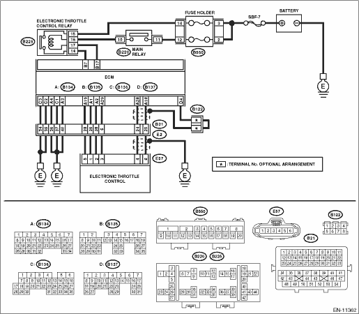
Wiring diagram:
Engine electrical system Engine Electrical System">
| STEP | CHECK | YES | NO |
1.CHECK HARNESS BETWEEN ECM AND ELECTRONIC THROTTLE CONTROL CONNECTOR.
1) Turn the ignition switch to OFF.
2) Disconnect the connector from ECM.
3) Disconnect the connectors from electronic throttle control.
4) Measure the resistance between ECM connector and chassis ground.
Connector & terminal
(B134) No. 19 — Chassis ground:
(B134) No. 18 — Chassis ground:
(B134) No. 18 — (B136) No. 4:
(B134) No. 28 — Chassis ground:
(B134) No. 28 — (B136) No. 4:
Is the resistance 1 M? or more?
Diagnostic Procedure with Diagnostic Trouble Code (DTC) > DTC P2135 THROTTLE/PEDAL POSITION SENSOR/SWITCH "A"/"B" VOLTAGE CORRELATION">Go to Step 2.
Repair the ground short circuit of harness between ECM connector and electronic throttle control connector.
2.CHECK SHORT CIRCUIT INSIDE THE ECM.
1) Connect the connector to ECM.
2) Measure the resistance between electronic throttle control connector and engine ground.
Connector & terminal
(E57) No. 6 — Engine ground:
(E57) No. 4 — Engine ground:
Is the resistance 1 M? or more?
Diagnostic Procedure with Diagnostic Trouble Code (DTC) > DTC P2135 THROTTLE/PEDAL POSITION SENSOR/SWITCH "A"/"B" VOLTAGE CORRELATION">Go to Step 3.
Repair the ground short circuit of harness between ECM connector and electronic throttle control connector. Replace the ECM if defective. Engine Control Module (ECM)">
3.CHECK HARNESS BETWEEN ECM AND ELECTRONIC THROTTLE CONTROL CONNECTOR.
1) Disconnect the connector from ECM.
2) Measure the resistance of harness between ECM connector and electronic throttle control connector.
Connector & terminal
(B134) No. 18 — (E57) No. 6:
(B134) No. 28 — (E57) No. 4:
(B134) No. 29 — (E57) No. 3:
Is the resistance less than 1 ??
Diagnostic Procedure with Diagnostic Trouble Code (DTC) > DTC P2135 THROTTLE/PEDAL POSITION SENSOR/SWITCH "A"/"B" VOLTAGE CORRELATION">Go to Step 4.
Repair the harness and connector.
NOTE:
In this case, repair the following item:
• Open circuit in harness between ECM connector and electronic throttle control connector
• Poor contact of coupling connector
4.CHECK HARNESS BETWEEN ECM AND ELECTRONIC THROTTLE CONTROL CONNECTOR.
1) Connect the connector to ECM.
2) Measure the resistance between electronic throttle control connector and engine ground.
Connector & terminal
(E57) No. 3 — Engine ground:
Is the resistance less than 5 ??
Diagnostic Procedure with Diagnostic Trouble Code (DTC) > DTC P2135 THROTTLE/PEDAL POSITION SENSOR/SWITCH "A"/"B" VOLTAGE CORRELATION">Go to Step 5.
Repair the harness and connector.
NOTE:
In this case, repair the following item:
• Open circuit of harness between ECM connector and engine ground
• Poor contact of ECM connector
• Poor contact of coupling connector
5.CHECK HARNESS BETWEEN ECM AND ELECTRONIC THROTTLE CONTROL CONNECTOR.
1) Turn the ignition switch to ON.
2) Measure the voltage between electronic throttle control connector and engine ground.
Connector & terminal
(E57) No. 6 (+) — Engine ground (−):
(E57) No. 4 (+) — Engine ground (−):
Is the voltage 5 V or more?
Repair the short circuit to power in the harness between ECM connector and electronic throttle control connector.
Diagnostic Procedure with Diagnostic Trouble Code (DTC) > DTC P2135 THROTTLE/PEDAL POSITION SENSOR/SWITCH "A"/"B" VOLTAGE CORRELATION">Go to Step 6.
6.CHECK HARNESS BETWEEN ECM AND ELECTRONIC THROTTLE CONTROL CONNECTOR.
1) Turn the ignition switch to OFF.
2) Disconnect the connector from ECM.
3) Measure the resistance between ECM connectors.
Connector & terminal
(B134) No. 19 — (B134) No. 18:
(B134) No. 19 — (B134) No. 28:
Is the resistance 1 M? or more?
Repair the poor contact of electronic throttle control connector. Replace the electronic throttle control if defective. Throttle Body">
Repair the short circuit to power in the harness between ECM connector and electronic throttle control connector.
1. OUTLINE OF DIAGNOSIS
Judge as NG when the signal level of throttle position sensor 1 is different from the throttle position sensor 2.
2. COMPONENT DESCRIPTION
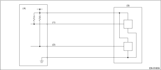
(1) | Throttle position sensor 1 signal | (3) | Throttle position sensor | (4) | Engine control module (ECM) |
(2) | Throttle position sensor 2 signal |
3. EXECUTION CONDITION
Secondary Parameters | Execution condition |
Ignition switch | ON |
Battery voltage | ≥ 6 V |
4. GENERAL DRIVING CYCLE
Always perform the diagnosis continuously.
5. DIAGNOSTIC METHOD
If the duration of time while the following conditions are met is longer than the time indicated, judge as NG.
Malfunction Criteria | Threshold Value |
Signal difference between two sensors | Within NG range of Details of Judgment value |
Details of Judgment Value
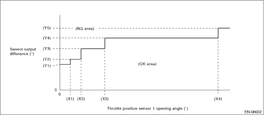
(X1) | 2.125 ° | (X2) | 4.25 ° | (X3) | 9 ° |
(X4) | 31.625 ° | ||||
(Y1) | 4.736 ° | (Y2) | 5.736 ° | (Y3) | 7.861 ° |
(Y4) | 9.986 ° | (Y5) | 11.986 ° |
Time Needed for Diagnosis: 212 ms
Malfunction Indicator Light Illumination: Illuminates as soon as a malfunction occurs.
 Dtc p2128 throttle/pedal position sensor/switch "e" circuit high
ENGINE (DIAGNOSTICS)(H4DO) > Diagnostic Procedure with Diagnostic Trouble Code (DTC)DTC P2128 THROTTLE/PEDAL POSITION SENSOR/SWITCH "E" CIRCUIT HIGHDTC detecting condition:Immediately at ...
 Dtc p2138 throttle/pedal position sensor/switch "d"/"e" voltage correlation
ENGINE (DIAGNOSTICS)(H4DO) > Diagnostic Procedure with Diagnostic Trouble Code (DTC)DTC P2138 THROTTLE/PEDAL POSITION SENSOR/SWITCH "D"/"E" VOLTAGE CORRELATIONDTC DETECTING COND ...
Other materials:
Dtc b1907 short in front p/t lh (to ground)
AIRBAG SYSTEM (DIAGNOSTICS) > Diagnostic Chart with Trouble CodeDTC B1907 SHORT IN FRONT P/T LH (TO GROUND)Diagnosis start condition:Ignition voltage is 10 V to 16 V.DTC detecting condition:• Seat belt pretensioner (LH) circuit is shorted to ground.• Pretensioner (LH) is faulty.• ...
Hazard warning flasher
Models without multi function display
Models with multi function display
The hazard warning flasher is used to
warn other drivers when you have to park your vehicle under emergency
conditions.
The hazard warning flasher works regardless
of the position of the ignition switch.
To ...
Removal
CONTINUOUSLY VARIABLE TRANSMISSION(TR580) > Drive PlateREMOVAL1. Remove the transmission assembly from the vehicle. Automatic Transmission Assembly > REMOVAL">2. Set the ST.ST 498497300CRANKSHAFT STOPPER3. Remove the drive plate and reinforcement drive plate. ...
