Subaru Crosstrek Service Manual: Dtc p2138 throttle/pedal position sensor/switch "d"/"e" voltage correlation
ENGINE (DIAGNOSTICS)(H4DO) > Diagnostic Procedure with Diagnostic Trouble Code (DTC)
DTC P2138 THROTTLE/PEDAL POSITION SENSOR/SWITCH "D"/"E" VOLTAGE CORRELATION
DTC DETECTING CONDITION:
Immediately at fault recognition
TROUBLE SYMPTOM:
• Improper idling
• Poor driving performance
CAUTION:
After servicing or replacing faulty parts, perform Clear Memory Mode Clear Memory Mode > OPERATION"> , and Inspection Mode Inspection Mode > PROCEDURE">.
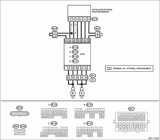
WIRING DIAGRAM:
Engine electrical system Engine Electrical System">
| STEP | CHECK | YES | NO |
1.CHECK ACCELERATOR PEDAL POSITION SENSOR OUTPUT.
1) Turn the ignition switch to ON.
2) Measure the voltage between ECM connector and chassis ground.
Connector & terminal
Main accelerator pedal position sensor signal
(B135) No. 23 (+) — Chassis ground (−):
Sub accelerator pedal position sensor signal
(B135) No. 31 (+) — Chassis ground (−):
Is the difference in measured values for the main accelerator pedal position sensor signal and the sub accelerator pedal position sensor signal 0 V?
Diagnostic Procedure with Diagnostic Trouble Code (DTC) > DTC P2138 THROTTLE/PEDAL POSITION SENSOR/SWITCH "D"/"E" VOLTAGE CORRELATION">Go to Step 3.
Diagnostic Procedure with Diagnostic Trouble Code (DTC) > DTC P2138 THROTTLE/PEDAL POSITION SENSOR/SWITCH "D"/"E" VOLTAGE CORRELATION">Go to Step 2.
2.CHECK ACCELERATOR PEDAL POSITION SENSOR OUTPUT.
1) Measure the voltage between accelerator pedal position sensor connector and chassis ground.
Connector & terminal
(B315) No. 6 (+) — Chassis ground (−):
(B315) No. 3 (+) — Chassis ground (−):
Is the difference in measured values for the main accelerator pedal position sensor signal and the sub accelerator pedal position sensor signal 0 V?
Replace the accelerator pedal. Accelerator Pedal">
Repair the harness and connector.
NOTE:
In this case, repair the following item:
• Open circuit of harness between ECM connector and accelerator pedal position sensor connector
• Short circuit to ground in harness between ECM connector and accelerator pedal position sensor connector
3.CHECK HARNESS BETWEEN ECM AND ACCELERATOR PEDAL POSITION SENSOR CONNECTOR.
Measure the resistance of harness between accelerator pedal position sensor connector and chassis ground.
Connector & terminal
(B315) No. 5 — Chassis ground:
(B315) No. 2 — Chassis ground:
Is the resistance less than 5 ??
Repair the poor contact of ECM connector.
Repair the harness and connector.
NOTE:
In this case, repair the following item:
• Open circuit of harness between ECM connector and accelerator pedal position sensor connector
• Open circuit of harness between ECM connector and engine ground
• Poor contact of ECM connector
• Poor contact of joint connector
1. OUTLINE OF DIAGNOSIS
Judge as NG when the signal level of accelerator pedal position sensor 1 is different from the accelerator pedal position sensor 2.
2. COMPONENT DESCRIPTION
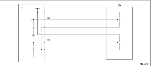
(1) | Engine control module (ECM) | (3) | Accelerator pedal position sensor 2 signal | (4) | Accelerator pedal position sensor |
(2) | Accelerator pedal position sensor 1 signal |
3. EXECUTION CONDITION
Secondary Parameters | Execution condition |
Battery voltage | ≥ 6 V |
4. GENERAL DRIVING CYCLE
Always perform the diagnosis continuously.
5. DIAGNOSTIC METHOD
If the duration of time while the following conditions are met is longer than the time indicated, judge as NG.
Malfunction Criteria | Threshold Value |
Signal difference between two sensors | Within NG range of Details of Judgment value |
Details of Judgment Value
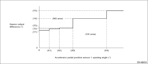
(X1) | 0.6 ° | (X2) | 1.2 ° | (X3) | 2 ° |
(X4) | 4 ° | ||||
(Y1) | 1.465 ° | (Y2) | 1.597 ° | (Y3) | 1.663 ° |
(Y4) | 2.455 ° | (Y5) | 3.116 ° |
Time Needed for Diagnosis: 116 ms
Malfunction Indicator Light Illumination: Illuminates as soon as a malfunction occurs.
 Dtc p2135 throttle/pedal position sensor/switch "a"/"b" voltage correlation
ENGINE (DIAGNOSTICS)(H4DO) > Diagnostic Procedure with Diagnostic Trouble Code (DTC)DTC P2135 THROTTLE/PEDAL POSITION SENSOR/SWITCH "A"/"B" VOLTAGE CORRELATIONDTC detecting cond ...
 Dtc p2195 a/f /o2 sensor signal biased/stuck lean bank 1 sensor 1
ENGINE (DIAGNOSTICS)(H4DO) > Diagnostic Procedure with Diagnostic Trouble Code (DTC)DTC P2195 A/F /O2 SENSOR SIGNAL BIASED/STUCK LEAN BANK 1 SENSOR 1DTC detecting condition:Detected when two consec ...
Other materials:
Terms
Packet write
This is a general term that describes
the process of writing data on-demand to
CD-R, etc., in the same way that data is
written to floppy or hard discs.
ID3 tag
This is a method of embedding trackrelated
information in an MP3 file. This
embedded information can incl ...
Installation
MANUAL TRANSMISSION AND DIFFERENTIAL(5MT) > Shifter Fork and RodINSTALLATION1. Install the check ball spring and check ball to the reverse fork rod arm, and press in the ST.ST 399411700ACCENT BALL INSTALLER2. Install the reverse fork rod through the hole on the rear of the transmission case. P ...
Dtc b2275 engine start request control circuit
KEYLESS ACCESS WITH PUSH BUTTON START SYSTEM (DIAGNOSTICS) > Diagnostic Procedure with Diagnostic Trouble Code (DTC)DTC B2275 ENGINE START REQUEST CONTROL CIRCUITDTC detecting condition:• When malfunction is detected in engine start permission signal output circuit in the keyless access CM. ...
