Subaru Crosstrek Service Manual: Dtc p2128 throttle/pedal position sensor/switch "e" circuit high
ENGINE (DIAGNOSTICS)(H4DO) > Diagnostic Procedure with Diagnostic Trouble Code (DTC)
DTC P2128 THROTTLE/PEDAL POSITION SENSOR/SWITCH "E" CIRCUIT HIGH
DTC detecting condition:
Immediately at fault recognition
Trouble symptom:
• Improper idling
• Poor driving performance
CAUTION:
After servicing or replacing faulty parts, perform Clear Memory Mode Clear Memory Mode > OPERATION"> , and Inspection Mode Inspection Mode > PROCEDURE">.
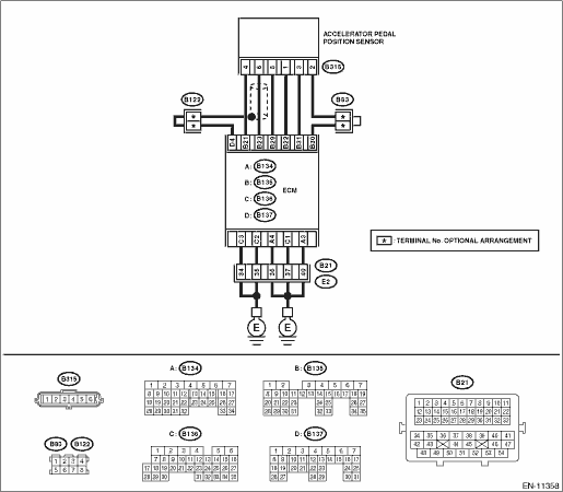
Wiring diagram:
Engine electrical system Engine Electrical System">
| STEP | CHECK | YES | NO |
1.CHECK HARNESS BETWEEN ECM AND ACCELERATOR PEDAL POSITION SENSOR CONNECTOR.
1) Turn the ignition switch to OFF.
2) Disconnect the connector from ECM.
3) Disconnect the connector from the accelerator pedal position sensor.
4) Measure the resistance of harness between ECM connector and accelerator pedal position sensor connector.
Connector & terminal
(B135) No. 31 — (B315) No. 3:
(B135) No. 30 — (B315) No. 2:
Is the resistance less than 1 ??
Diagnostic Procedure with Diagnostic Trouble Code (DTC) > DTC P2128 THROTTLE/PEDAL POSITION SENSOR/SWITCH "E" CIRCUIT HIGH">Go to Step 2.
Repair the harness and connector.
NOTE:
In this case, repair the following item:
• Open circuit of harness between ECM connector and accelerator pedal position sensor connector
• Poor contact of joint connector
2.CHECK HARNESS BETWEEN ECM AND ACCELERATOR PEDAL POSITION SENSOR CONNECTOR.
1) Connect the connector to ECM.
2) Measure the resistance between accelerator pedal position sensor connector and chassis ground.
Connector & terminal
(B315) No. 2 — Chassis ground:
Is the resistance less than 1 ??
Diagnostic Procedure with Diagnostic Trouble Code (DTC) > DTC P2128 THROTTLE/PEDAL POSITION SENSOR/SWITCH "E" CIRCUIT HIGH">Go to Step 3.
Repair the harness and connector.
NOTE:
In this case, repair the following item:
• Open circuit of harness between ECM connector and engine ground
• Poor contact of ECM connector
• Poor contact of coupling connector
3.CHECK HARNESS BETWEEN ECM AND ACCELERATOR PEDAL POSITION SENSOR CONNECTOR.
1) Turn the ignition switch to ON.
2) Measure the voltage between accelerator pedal position sensor connector and chassis ground.
Connector & terminal
(B315) No. 3 (+) — Chassis ground (−):
Is the voltage 5 V or more?
Repair the short circuit to power supply in harness between ECM connector and accelerator pedal position sensor connector.
Diagnostic Procedure with Diagnostic Trouble Code (DTC) > DTC P2128 THROTTLE/PEDAL POSITION SENSOR/SWITCH "E" CIRCUIT HIGH">Go to Step 4.
4.CHECK HARNESS BETWEEN ECM AND ACCELERATOR PEDAL POSITION SENSOR CONNECTOR.
1) Turn the ignition switch to OFF.
2) Disconnect the connector from ECM.
3) Measure the resistance between ECM connectors.
Connector & terminal
(B135) No. 22 — (B135) No. 31:
Is the resistance 1 M? or more?
Repair the poor contact of accelerator pedal position sensor connector. Replace the accelerator pedal if defective. Accelerator Pedal">
Repair the short circuit to power supply in harness between ECM connector and accelerator pedal position sensor connector.
1. OUTLINE OF DIAGNOSIS
Detect the open or short circuit of accelerator pedal position sensor 2.
Judge as NG if out of specification.
2. COMPONENT DESCRIPTION
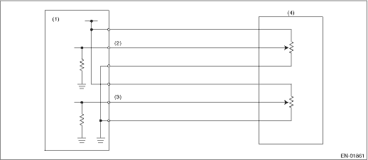
(1) | Engine control module (ECM) | (3) | Accelerator pedal position sensor 2 signal | (4) | Accelerator pedal position sensor |
(2) | Accelerator pedal position sensor 1 signal |
3. EXECUTION CONDITION
Secondary Parameters | Execution condition |
Battery voltage | ≥ 6 V |
4. GENERAL DRIVING CYCLE
Always perform the diagnosis continuously.
5. DIAGNOSTIC METHOD
If the duration of time while the following conditions are met is longer than the time indicated, judge as NG.
Malfunction Criteria | Threshold Value |
Sensor 2 input voltage | ≥ 4.737 V |
Time Needed for Diagnosis: 100 ms
Malfunction Indicator Light Illumination: Illuminates as soon as a malfunction occurs.
 Dtc p2127 throttle/pedal position sensor/switch "e" circuit low
ENGINE (DIAGNOSTICS)(H4DO) > Diagnostic Procedure with Diagnostic Trouble Code (DTC)DTC P2127 THROTTLE/PEDAL POSITION SENSOR/SWITCH "E" CIRCUIT LOWDTC detecting condition:Immediately at f ...
 Dtc p2135 throttle/pedal position sensor/switch "a"/"b" voltage correlation
ENGINE (DIAGNOSTICS)(H4DO) > Diagnostic Procedure with Diagnostic Trouble Code (DTC)DTC P2135 THROTTLE/PEDAL POSITION SENSOR/SWITCH "A"/"B" VOLTAGE CORRELATIONDTC detecting cond ...
Other materials:
Seatbelt with shoulder belt and lap belt pretensioners
NOTE
This section applies specifically to the following Subaru Ascent components.
Driver's seatbelt
Front passenger's seatbelt
Seatbelt retractor assembly (shoulder belt pretensioner and adaptive force
limiter)
Lap belt pretensioner
When the pretensioners in the Suba ...
Dtc u0122 lost communication with vehicle dynamics control module
POWER ASSISTED SYSTEM (POWER STEERING) (DIAGNOSTICS) > Diagnostic Procedure with Diagnostic Trouble Code (DTC)DTC U0122 LOST COMMUNICATION WITH VEHICLE DYNAMICS CONTROL MODULENOTE:Refer to “LAN SYSTEM” for diagnostic procedure. Basic Diagnostic Procedure"> ...
Triple meter screen
Triple meter screen (display example)
This screen displays up to three optional
pieces of information that can be selected
from the following items.
The items shown in the triple meter screen
can be changed. For details, refer to
"Triple meter setting"
Item
Details
...
