Subaru Crosstrek Service Manual: Dtc p2127 throttle/pedal position sensor/switch "e" circuit low
ENGINE (DIAGNOSTICS)(H4DO) > Diagnostic Procedure with Diagnostic Trouble Code (DTC)
DTC P2127 THROTTLE/PEDAL POSITION SENSOR/SWITCH "E" CIRCUIT LOW
DTC detecting condition:
Immediately at fault recognition
Trouble symptom:
• Improper idling
• Poor driving performance
CAUTION:
After servicing or replacing faulty parts, perform Clear Memory Mode Clear Memory Mode > OPERATION"> , and Inspection Mode Inspection Mode > PROCEDURE">.
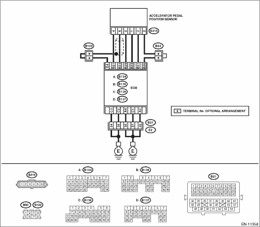
Wiring diagram:
Engine electrical system Engine Electrical System">
| STEP | CHECK | YES | NO |
1.CHECK HARNESS BETWEEN ECM AND ACCELERATOR PEDAL POSITION SENSOR CONNECTOR.
1) Turn the ignition switch to OFF.
2) Disconnect the connector from ECM.
3) Disconnect the connector from the accelerator pedal position sensor.
4) Measure the resistance between ECM connector and chassis ground.
Connector & terminal
(B135) No. 22 — Chassis ground:
(B135) No. 31 — Chassis ground:
Is the resistance 1 M? or more?
Diagnostic Procedure with Diagnostic Trouble Code (DTC) > DTC P2127 THROTTLE/PEDAL POSITION SENSOR/SWITCH "E" CIRCUIT LOW">Go to Step 2.
Repair the short circuit to ground in harness between ECM connector and accelerator pedal position sensor connector.
2.CHECK SHORT CIRCUIT INSIDE THE ECM.
1) Connect the connector to ECM.
2) Measure the resistance between accelerator pedal position sensor connector and chassis ground.
Connector & terminal
(B315) No. 3 — Chassis ground:
Is the resistance 1 M? or more?
Replace the accelerator pedal. Accelerator Pedal">
Repair the short circuit to ground in harness between ECM connector and accelerator pedal position sensor connector. Replace the ECM if defective. Engine Control Module (ECM)">
1. OUTLINE OF DIAGNOSIS
Detect the open or short circuit of accelerator pedal position sensor 2.
Judge as NG if out of specification.
2. COMPONENT DESCRIPTION

(1) | Engine control module (ECM) | (3) | Accelerator pedal position sensor 2 signal | (4) | Accelerator pedal position sensor |
(2) | Accelerator pedal position sensor 1 signal |
3. EXECUTION CONDITION
Secondary Parameters | Execution condition |
Battery voltage | ≥ 6 V |
4. GENERAL DRIVING CYCLE
Always perform the diagnosis continuously.
5. DIAGNOSTIC METHOD
If the duration of time while the following conditions are met is longer than the time indicated, judge as NG.
Malfunction Criteria | Threshold Value |
Sensor 2 input voltage | < 0.298 V |
Time Needed for Diagnosis: 100 ms
Malfunction Indicator Light Illumination: Illuminates as soon as a malfunction occurs.
 Dtc p2123 throttle/pedal position sensor/switch "d" circuit high
ENGINE (DIAGNOSTICS)(H4DO) > Diagnostic Procedure with Diagnostic Trouble Code (DTC)DTC P2123 THROTTLE/PEDAL POSITION SENSOR/SWITCH "D" CIRCUIT HIGHDTC detecting condition:Immediately at ...
 Dtc p2128 throttle/pedal position sensor/switch "e" circuit high
ENGINE (DIAGNOSTICS)(H4DO) > Diagnostic Procedure with Diagnostic Trouble Code (DTC)DTC P2128 THROTTLE/PEDAL POSITION SENSOR/SWITCH "E" CIRCUIT HIGHDTC detecting condition:Immediately at ...
Other materials:
Tire pressure monitoring system (TPMS) (U.S.-spec. models)
Low tire pressure warning light (type A)
Low tire pressure warning light (type B)
The tire pressure monitoring system provides
the driver with a warning message
when tire pressure is severely low.
The tire pressure monitoring system will
activate only when the vehicle is driven at
s ...
Disassembly
CONTINUOUSLY VARIABLE TRANSMISSION(TR580) > Forward Clutch AssemblyDISASSEMBLY1. FORWARD CLUTCH ASSEMBLY1. Remove the snap ring.2. Remove the retaining plate, drive plate, driven plate and dish plate.3. Compress the return spring using the ST to remove the snap ring.ST1 18762AA010COMPRESSOR SP ...
Adjustment
LIGHTING SYSTEM > Front Fog Light AssemblyADJUSTMENT1. FOG LIGHT AIMING1. Before checking the fog light assembly - front beam level, be sure of the following:• The area around the fog light assembly - front has not sustained any scratches, damage or other type of deformation.• The veh ...
