Subaru Crosstrek Service Manual: Component
STARTING/CHARGING SYSTEMS(H4DO) > General Description
COMPONENT
1. STARTER
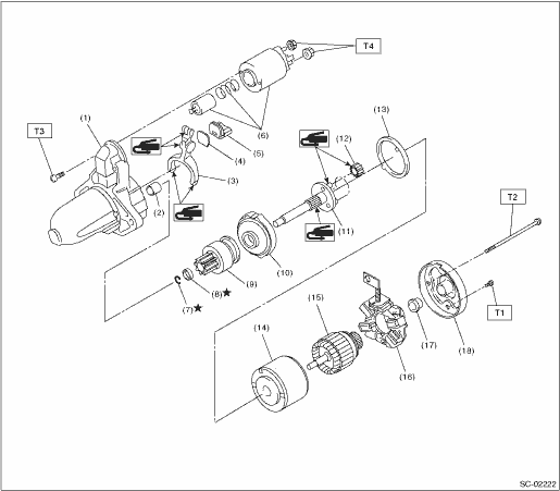
(1) | Starter housing ASSY | (9) | Overrunning clutch | (17) | Sleeve bearing |
(2) | Sleeve bearing | (10) | Internal gear ASSY | (18) | Starter cover ASSY |
(3) | Shift lever | (11) | Shaft | ||
(4) | Plate | (12) | Pinion gear | Tightening torque: N·m (kgf-m, ft-lb) | |
(5) | Seal rubber | (13) | Seal rubber | T1: | 1.4 (0.1, 1.0) |
(6) | Magnet switch ASSY | (14) | Yoke ASSY | T2: | 6 (0.6, 4.4) |
(7) | Snap ring | (15) | Armature ASSY | T3: | 7.5 (0.8, 5.5) |
(8) | Stopper | (16) | Brush holder ASSY | T4: | 10 (1.0, 7.4) |
2. GENERATOR
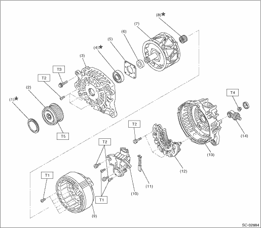
(1) | Cap | (8) | Bearing | Tightening torque: N·m (kgf-m, ft-lb) | |
(2) | Pulley | (9) | Stator coil | T1: | 2 (0.2, 1.5) |
(3) | Front cover | (10) | IC regulator | T2: | 3.9 (0.4, 2.9) |
(4) | Ball bearing | (11) | Brush | T3: | 4.4 (0.4, 3.2) |
(5) | Bearing retainer | (12) | Rectifier | T4: | 8.9 (0.9, 6.6) |
(6) | Spacer | (13) | Rear cover | T5: | 108 (11.0, 79.8) |
(7) | Rotor | (14) | Terminal B | ||
3. GENERATOR BRACKET
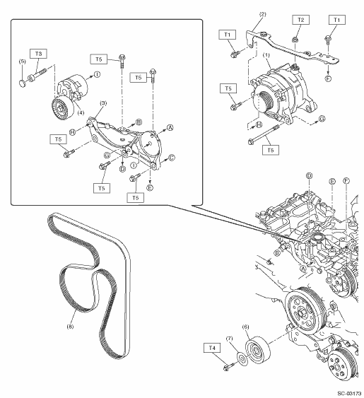
(1) | Generator | (7) | Idler pulley cover | Tightening torque: N·m (kgf-m, ft-lb) | |
(2) | V-belt cover bracket | (8) | V-belt | T1: | 6.4 (0.7, 4.7) |
(3) | Generator bracket | T2: | 15.5 (1.6, 11.4) | ||
(4) | V-belt tensioner ASSY | T3: | 25 (2.5, 18.4) | ||
(5) | Cap | T4: | 36 (3.7, 26.6) | ||
(6) | Idler pulley | T5: | Generator > INSTALLATION"> | ||

4. BATTERY CURRENT & TEMPERATURE SENSOR
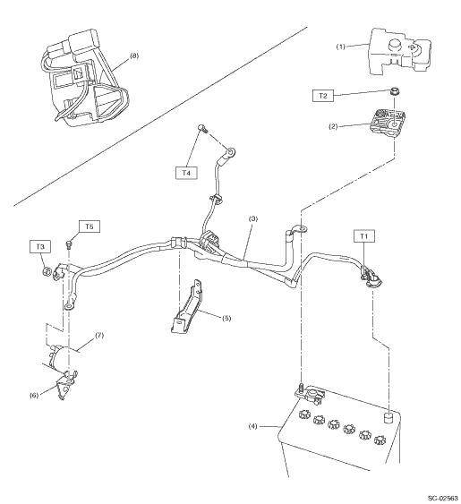
(1) | Terminal boot | (7) | Starter | Tightening torque: N·m (kgf-m, ft-lb) | |
(2) | Terminal fuse ASSY | (8) | Battery temperature sensor | T1: | 6 (0.6, 4.4) |
(3) | Battery cable ASSY | T2: | 7.5 (0.8, 5.5) | ||
(4) | Battery | T3: | 11 (1.1, 8.1) | ||
(5) | Battery cable bracket | T4: | 13 (1.3, 9.6) | ||
(6) | Battery cable stay | T5: | 14 (1.4, 10.3) | ||
 Specification
STARTING/CHARGING SYSTEMS(H4DO) > General DescriptionSPECIFICATIONItemSpecificationsVehicle modelCVTMTStarterTypeReduction typeModelM000T38571M000T33176ManufacturerMitsubishi ElectricVoltage and ou ...
 Preparation tool
STARTING/CHARGING SYSTEMS(H4DO) > General DescriptionPREPARATION TOOL1. GENERAL TOOLTOOL NAMEREMARKSCircuit testerUsed for measuring resistance, voltage and current.NOTE:• For measuring stand ...
Other materials:
Basic diagnostic procedure Procedure
VEHICLE DYNAMICS CONTROL (VDC) (DIAGNOSTICS) > Basic Diagnostic ProcedurePROCEDURECAUTION:Remove foreign matter (dust, water, oil etc.) from the VDCCM&H/U connector during removal and installation.NOTE:• To check the harness for open or short circuits, shake problem spot or connector.&b ...
Inspection
FUEL INJECTION (FUEL SYSTEMS)(H4DO) > Throttle BodyINSPECTION1. THROTTLE SENSOR (METHOD WITH CIRCUIT TESTER)1. Remove the glove box. Glove Box > REMOVAL">2. Turn the ignition switch to ON. (engine OFF)3. Measure the voltage between ECM connector terminals.(A)To ECM connector Thrott ...
Capacity
SPECIFICATIONS > CrosstrekCAPACITYModel2.0 L DOHC non-turbo5MTCVTFuel tankL (US gal, Imp gal)60 (15.9, 13.2)Engine oilTotal capacity (at overhaul)L (US qt, Imp qt)5.7 (6.0, 5.0)Filling amount of engine oilL (US qt, Imp qt)When replacing engine oil and oil filter4.8 (5.1, 4.2)When replacing engine ...
