Subaru Crosstrek Service Manual: Removal
CONTINUOUSLY VARIABLE TRANSMISSION(TR580) > Front Differential Assembly
REMOVAL
1. Remove the transmission assembly from the vehicle. Automatic Transmission Assembly > REMOVAL">
2. Remove the air breather hose. Air Breather Hose > REMOVAL">
3. Remove the control valve body. Control Valve Body > REMOVAL">
4. Remove the transmission harness. Transmission Harness > REMOVAL">
5. Remove the turbine speed sensor. Turbine Speed Sensor > REMOVAL">
6. Remove the secondary speed sensor. Secondary Speed Sensor > REMOVAL">
7. Remove the primary speed sensor. Primary Speed Sensor > REMOVAL">
8. Remove the inhibitor switch. Inhibitor Switch > REMOVAL">
9. Remove the extension case. Extension Case > REMOVAL">
10. Remove the transfer clutch assembly. Transfer Clutch > REMOVAL">
11. Remove the transfer driven gear assembly. Transfer Driven Gear > REMOVAL">
12. Remove the parking pawl. Parking Pawl > REMOVAL">
13. Remove the reduction driven gear assembly. Reduction Driven Gear > REMOVAL">
14. Remove the oil pan and oil strainer. Oil Pan and Strainer > REMOVAL">
15. Remove the transmission control device. Transmission Control Device > REMOVAL">
16. Remove the transmission case. Transmission Case > REMOVAL">
17. Remove the reduction drive gear. Reduction Drive Gear > REMOVAL">
18. Remove the primary pulley, secondary pulley and variator chain. Primary Pulley and Secondary Pulley > REMOVAL">
19. Remove the reverse brake assembly. Reverse Brake Assembly > REMOVAL">
20. Remove the forward clutch assembly. Forward Clutch Assembly > REMOVAL">
21. Remove the drive pinion shaft assembly. Drive Pinion Shaft Assembly > REMOVAL">
22. Remove the oil baffle.

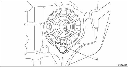
23. Remove the lock plates on both sides.

(A) | Lock plate |
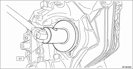
24. Remove the differential side retainers using ST.
NOTE:
• When the wrench COMPL retainer interferes with the converter case, align the cutout portion with the interference part.
• Support the differential case assembly by hand to avoid damaging the retainer mounting hole of the converter case.
• Keep the left and right differential side retainers and left and right bearing outer races by attaching tags or in similar ways to make it possible to identify RH and LH sides.
| ST 18658AA020 | WRENCH COMPL RETAINER |

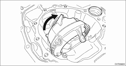
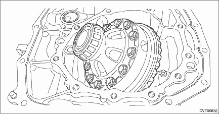
25. Remove the front differential assembly while being careful not to damage the attachment part of the retainer.

26. Remove the oil seals and O-rings from both differential side retainers. Front Differential Assembly > DISASSEMBLY">
 Adjustment
CONTINUOUSLY VARIABLE TRANSMISSION(TR580) > Front Differential AssemblyADJUSTMENT1. Using the ST, screw-in the retainer until resistance is felt.NOTE:RH side should be screwed-in more than LH side. ...
 Assembly
CONTINUOUSLY VARIABLE TRANSMISSION(TR580) > Front Differential AssemblyASSEMBLY1. DIFFERENTIAL CASE ASSEMBLY1. Install the washer and differential bevel gear into the differential case (RH).2. Inst ...
Other materials:
Removal
CONTINUOUSLY VARIABLE TRANSMISSION(TR580) > Secondary Speed SensorREMOVALCAUTION:• Be sure to prevent water or oil from contacting the connector terminal of secondary speed sensor. If adhesion occurs, replace with a new part.• When secondary speed sensor is removed, CVTF leaks. After ...
Installation
MECHANICAL(H4DO) > Crank PulleyINSTALLATION1. Degrease the press-fit section for the chain cover front oil seal, and install the front oil seal to the chain cover using ST.CAUTION:Do not apply fluid such as engine oil to the front oil seal and the chain cover; otherwise engine oil leakage may occ ...
Caution
OCCUPANT DETECTION SYSTEM (DIAGNOSTICS) > General DescriptionCAUTION1. The occupant detection system (passenger seat only) control module and the occupant detection sensor are fixed to the seat cushion frame. Never remove the occupant detection control module or the occupant detection sensor from ...
