Subaru Crosstrek Service Manual: Dtc p2123 throttle/pedal position sensor/switch "d" circuit high
ENGINE (DIAGNOSTICS)(H4DO) > Diagnostic Procedure with Diagnostic Trouble Code (DTC)
DTC P2123 THROTTLE/PEDAL POSITION SENSOR/SWITCH "D" CIRCUIT HIGH
DTC detecting condition:
Immediately at fault recognition
Trouble symptom:
• Improper idling
• Poor driving performance
CAUTION:
After servicing or replacing faulty parts, perform Clear Memory Mode Clear Memory Mode > OPERATION"> , and Inspection Mode Inspection Mode > PROCEDURE">.
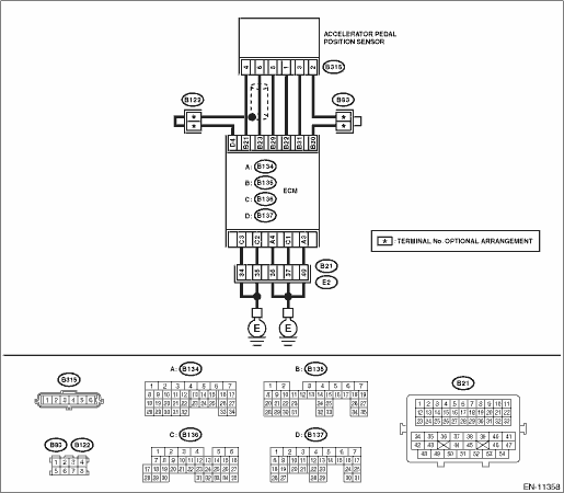
Wiring diagram:
Engine electrical system Engine Electrical System">
| STEP | CHECK | YES | NO |
1.CHECK HARNESS BETWEEN ECM AND ACCELERATOR PEDAL POSITION SENSOR CONNECTOR.
1) Turn the ignition switch to OFF.
2) Disconnect the connector from ECM.
3) Disconnect the connector from the accelerator pedal position sensor.
4) Measure the resistance of harness between ECM connector and accelerator pedal position sensor connector.
Connector & terminal
(B135) No. 23 — (B315) No. 6:
(B135) No. 29 — (B315) No. 5:
Is the resistance less than 1 ??
Diagnostic Procedure with Diagnostic Trouble Code (DTC) > DTC P2123 THROTTLE/PEDAL POSITION SENSOR/SWITCH "D" CIRCUIT HIGH">Go to Step 2.
Repair the open circuit of harness between ECM connector and accelerator pedal position sensor connector.
2.CHECK HARNESS BETWEEN ECM AND ACCELERATOR PEDAL POSITION SENSOR CONNECTOR.
1) Connect the connector to ECM.
2) Measure the resistance between accelerator pedal position sensor connector and chassis ground.
Connector & terminal
(B315) No. 5 — Chassis ground:
Is the resistance less than 5 ??
Diagnostic Procedure with Diagnostic Trouble Code (DTC) > DTC P2123 THROTTLE/PEDAL POSITION SENSOR/SWITCH "D" CIRCUIT HIGH">Go to Step 3.
Repair the harness and connector.
NOTE:
In this case, repair the following item:
• Open circuit of harness between ECM connector and engine ground
• Poor contact of ECM connector
• Poor contact of coupling connector
3.CHECK HARNESS BETWEEN ECM AND ACCELERATOR PEDAL POSITION SENSOR CONNECTOR.
1) Turn the ignition switch to ON.
2) Measure the voltage between accelerator pedal position sensor connector and chassis ground.
Connector & terminal
(B315) No. 6 (+) — Chassis ground (−):
Is the voltage 5 V or more?
Repair the short circuit to power supply in harness between ECM connector and accelerator pedal position sensor connector.
Diagnostic Procedure with Diagnostic Trouble Code (DTC) > DTC P2123 THROTTLE/PEDAL POSITION SENSOR/SWITCH "D" CIRCUIT HIGH">Go to Step 4.
4.CHECK HARNESS BETWEEN ECM AND ACCELERATOR PEDAL POSITION SENSOR CONNECTOR.
1) Turn the ignition switch to OFF.
2) Disconnect the connector from ECM.
3) Measure the resistance between ECM connectors.
Connector & terminal
(B135) No. 21 — (B135) No. 23:
Is the resistance 1 M? or more?
Repair the poor contact of accelerator pedal position sensor connector. Replace the accelerator pedal if defective. Accelerator Pedal">
Repair the short circuit to power supply in harness between ECM connector and accelerator pedal position sensor connector.
1. OUTLINE OF DIAGNOSIS
Detect the open or short circuit of accelerator pedal position sensor 1.
Judge as NG if out of specification.
2. COMPONENT DESCRIPTION
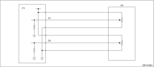
(1) | Engine control module (ECM) | (3) | Accelerator pedal position sensor 2 signal | (4) | Accelerator pedal position sensor |
(2) | Accelerator pedal position sensor 1 signal |
3. EXECUTION CONDITION
Secondary Parameters | Execution condition |
Battery voltage | ≥ 6 V |
4. GENERAL DRIVING CYCLE
Always perform the diagnosis continuously.
5. DIAGNOSTIC METHOD
If the duration of time while the following conditions are met is longer than the time indicated, judge as NG.
Malfunction Criteria | Threshold Value |
Sensor 1 input voltage | ≥ 4.737 V |
Time Needed for Diagnosis: 32 ms
Malfunction Indicator Light Illumination: Illuminates as soon as a malfunction occurs.
 Dtc p2122 throttle/pedal position sensor/switch "d" circuit low
ENGINE (DIAGNOSTICS)(H4DO) > Diagnostic Procedure with Diagnostic Trouble Code (DTC)DTC P2122 THROTTLE/PEDAL POSITION SENSOR/SWITCH "D" CIRCUIT LOWDTC detecting condition:Immediately at f ...
 Dtc p2127 throttle/pedal position sensor/switch "e" circuit low
ENGINE (DIAGNOSTICS)(H4DO) > Diagnostic Procedure with Diagnostic Trouble Code (DTC)DTC P2127 THROTTLE/PEDAL POSITION SENSOR/SWITCH "E" CIRCUIT LOWDTC detecting condition:Immediately at f ...
Other materials:
Inspection
MECHANICAL(H4DO) > Cylinder BlockINSPECTION1. CYLINDER BLOCK & PISTON1. Visually inspect to make sure that there are no cracks, scratches or other damage.2. Use liquid penetrant tester on the important sections to check for fissures.3. Check that there are no traces of gas leaking or water le ...
Diagnostic procedure with phenomenon
CRUISE CONTROL SYSTEM (DIAGNOSTICS) > Diagnostics with PhenomenonDIAGNOSTIC PROCEDURE WITH PHENOMENONPhenomenonCheck itemReference1CRUISE switch is not turned ON. (CRUISE indicator does not illuminate.) Or the cruise control is cancelled without CRUISE switch operation.(1) Perform cruise cancel c ...
Dtc b1642 side satellite sensor bus rh lost communication
AIRBAG SYSTEM (DIAGNOSTICS) > Diagnostic Chart with Trouble CodeDTC B1642 SIDE SATELLITE SENSOR BUS RH LOST COMMUNICATIONDiagnosis start condition:Ignition voltage is 10 V to 16 V.DTC detecting condition:• Open or short circuit in harness of side sensor bus (RH)• Side airbag sensor (R ...
