Subaru Crosstrek Service Manual: Installation
BRAKE > Rear Disc Brake Assembly
INSTALLATION
NOTE:
Before installation, remove mud and foreign matter from the caliper body assembly and support - rear disc brake.
1. Before installation, check each part. Rear Disc Brake Assembly > INSPECTION">
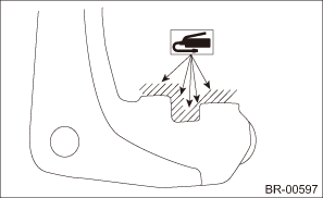
2. Apply a thin coat of grease to the support - rear disc brake.
Preparation items:
Grease: An item contained in the pad kit or equivalent
3. Install the support - rear disc brake to the housing assembly - rear axle.
Tightening torque:
Refer to “COMPONENT” of “General Description” for the tightening torque. General Description > COMPONENT">
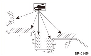
4. Apply a thin coat of grease to the pad clip.
Preparation items:
Grease: An item contained in the pad kit or equivalent
5. Apply a thin coat of grease to the shim - disc brake rear inner (a) and the shim - disc brake rear outer (b).
Preparation items:
Grease: Those contained in the pad kit or WAKO grease V160
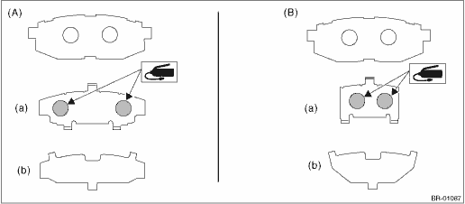
(A) | Pad - disc brake rear outer | (B) | Pad - disc brake rear inner |
6. Install the brake pad to the support - rear disc brake.
7. Install the caliper body assembly to the support - rear disc brake.
Tightening torque:
Caliper bolt: 27 N·m (2.75 kgf-m, 19.9 ft-lb)
8. Install the brake hose bracket.
Tightening torque:
Brake hose bracket: 33 N·m (3.36 kgf-m, 14.3 ft-lb)
9. Connect the brake hose using a new brake hose gasket.
Tightening torque:
Union bolt: 26 N·m (2.65 kgf-m, 19.2 ft-lb)
10. Bleed air from the brake system. Air Bleeding > PROCEDURE">
11. Install the rear wheels.
Tightening torque:
Except for C4 model: 120 N·m (12.24 kgf-m, 88.5 ft-lb)
C4 model: 100 N·m (10.20 kgf-m, 73.8 ft-lb)
 Inspection
BRAKE > Rear Disc Brake AssemblyINSPECTION1. Check the caliper body cylinder and piston - disc brake for uneven wear, damage or rust.2. Check the rubber parts for damage or deterioration.3. If faul ...
 Rear disc rotor
...
Other materials:
Headlight flasher
CAUTION
Do not hold the lever in the flashing
position for more than just a few
seconds.
To flash the headlights, pull the lever
toward you and then release it. The high
beam will stay on for as long as you hold
the lever. The headlight flasher works
even though the lighting switch is in ...
Procedure
HVAC SYSTEM (HEATER, VENTILATOR AND A/C) > Compressor OilPROCEDURENOTE:Before making repairs, perform the oil return operation to return the compressor oil in circulation with the refrigerant to the compressor assembly.1. Increase the engine speed to 1,500 r/min.2. Turn the A/C switch to ON.3. Tu ...
Disassembly
DRIVE SHAFT SYSTEM > Rear Drive ShaftDISASSEMBLY1. Remove the outer race (DOJ) from the shaft assembly.CAUTION:Be careful not to damage the boot.(1) Using a flat tip screwdriver or pliers, loosen the boot band on the large end of boot (DOJ).CAUTION:Be careful not to damage the boot.(2) Remove the ...
