Subaru Crosstrek Service Manual: Installation
AIRBAG SYSTEM > Side Airbag Module
INSTALLATION
CAUTION:
• Before handling the airbag system components, refer to “CAUTION” of “General Description” in “AIRBAG SYSTEM”. General Description > CAUTION">
• Make sure that the side airbag module is installed as shown in the figure.
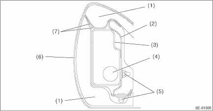
(1) | Pad ASSY - front seat backrest | (4) | Side airbag module inflator | (7) | Side airbag guide cloth |
(2) | Frame ASSY - front backrest | (5) | Nut | ||
(3) | Side airbag module protective cover | (6) | Cover COMPL - front backrest |
• Be careful not to stain or damage the cover COMPL - front backrest during assembly.
• Do not reuse hog rings.
• Secure the hog ring using hog ring pliers.
• Install the hog rings to the specified points securely and make sure that there is no wrinkle or twisting on the cover COMPL - front backrest.
1. Before installation, inspect the following items and replace any faulty part with a new one.
• Make sure that there is no foreign matter on side airbag module.
• Front seat, airbag module and mounting bracket are damaged or deformed.
• Harness and/or connector is cracked, deformed or open.
• Harness wire is exposed.
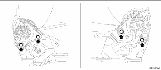
2. Install the side airbag module to the frame assembly - front backrest.
Tightening torque:
Side airbag module: 6 N·m (0.61 kgf-m, 4.4 ft-lb)
3. Install the side airbag harness to the frame assembly - front backrest.
4. Install the cover COMPL - front backrest.
5. Secure the backrest hinge.
Tightening torque:
Refer to “COMPONENT” of “General Description”. General Description > COMPONENT">
6. Install the side airbag harness to the back of the seat cushion assembly using a cable clip.
CAUTION:
After restoring the seat, operate the reclining and sliding mechanisms to check that the side airbag harness is not caught.
7. Install the front seat assembly to the body. Front Seat > INSTALLATION">
8. Connect the battery ground terminal. NOTE">

 Removal
AIRBAG SYSTEM > Side Airbag ModuleREMOVALCAUTION:Before handling the airbag system components, refer to “CAUTION” of “General Description” in “AIRBAG SYSTEM”. G ...
Other materials:
Air cleaner element
WARNING
Never operate the engine of your Subaru Ascent without the air cleaner element
installed. This component not only filters incoming air but also acts as a safety
barrier in case of engine backfire. Without it, flames could escape and cause serious
burns or injury.
CAUTION
When replac ...
Dtc p0751 shift solenoid "a" performance/stuck off
CONTINUOUSLY VARIABLE TRANSMISSION (DIAGNOSTICS) > Diagnostic Procedure with Diagnostic Trouble Code (DTC)DTC P0751 SHIFT SOLENOID "A" PERFORMANCE/STUCK OFFDTC detecting condition:Detected when two consecutive driving cycles with fault occur.Trouble symptom:• Shift control malfunc ...
Rear center seating position
CAUTION
The head restraint is not intended to
be used at the retracted position.
Before sitting on the seat, raise the
head restraint to the extended position.
Incorrect (retracted position)
Correct (extended position)
To raise:
Pull the head restraint up.
To lower:
Push ...
