Subaru Crosstrek Service Manual: Dtc p1499 coil 4 egr "a" control circuit high
ENGINE (DIAGNOSTICS)(H4DO) > Diagnostic Procedure with Diagnostic Trouble Code (DTC)
DTC P1499 COIL 4 EGR "A" CONTROL CIRCUIT HIGH
DTC detecting condition:
Immediately at fault recognition
Trouble symptom:
• Improper idling
• Poor driving performance
• Engine breathing
CAUTION:
After servicing or replacing faulty parts, perform Clear Memory Mode Clear Memory Mode > OPERATION"> , and Inspection Mode Inspection Mode > PROCEDURE">.
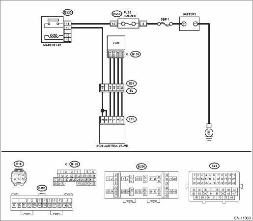
Wiring diagram:
Engine electrical system Engine Electrical System">
| STEP | CHECK | YES | NO |
1.CHECK HARNESS BETWEEN ECM AND EGR CONTROL VALVE CONNECTOR.
1) Turn the ignition switch to OFF.
2) Disconnect the connector from ECM.
3) Disconnect the connector from the EGR control valve.
4) Turn the ignition switch to ON.
5) Measure the voltage between ECM connector and chassis ground.
Connector & terminal
DTC P1493; (B136) No. 11 (+) — Chassis ground (−):
DTC P1495; (B136) No. 13 (+) — Chassis ground (−):
DTC P1497; (B136) No. 31 (+) — Chassis ground (−):
DTC P1499; (B136) No. 32 (+) — Chassis ground (−):
Is the voltage 10 V or more?
Repair the short circuit to power supply in the harness between the ECM connector and EGR control valve connector.
Diagnostic Procedure with Diagnostic Trouble Code (DTC) > DTC P1499 COIL 4 EGR "A" CONTROL CIRCUIT HIGH">Go to Step 2.
2.CHECK EGR CONTROL VALVE.
Measure the resistance between EGR control valve terminals.
Terminals
DTC P1493; No. 2 — No. 3:
DTC P1495; No. 2 — No. 1:
DTC P1497; No. 5 — No. 4:
DTC P1499; No. 5 — No. 6:
Is the resistance 20 ? or more?
Repair the poor contact of ECM connector.
Replace EGR control valve. EGR Control Valve">
1. OUTLINE OF DIAGNOSIS
NOTE:
For the detection standard, refer to DTC P1493. Diagnostic Procedure with Diagnostic Trouble Code (DTC) > DTC P1493 COIL 1 EGR "A" CONTROL CIRCUIT HIGH">
 Dtc p1498 coil 4 egr "a" control circuit low
ENGINE (DIAGNOSTICS)(H4DO) > Diagnostic Procedure with Diagnostic Trouble Code (DTC)DTC P1498 COIL 4 EGR "A" CONTROL CIRCUIT LOWDTC DETECTING CONDITION:Immediately at fault recognitionTRO ...
 Dtc p2004 tgv control stuck open bank 1
ENGINE (DIAGNOSTICS)(H4DO) > Diagnostic Procedure with Diagnostic Trouble Code (DTC)DTC P2004 TGV CONTROL STUCK OPEN BANK 1DTC DETECTING CONDITION:Immediately at fault recognitionCAUTION:After serv ...
Other materials:
General diagnostic table Inspection
PARKING BRAKE > General Diagnostic TableINSPECTIONSymptomsPossible causeCorrective actionBrake draggingLever assembly - hand brake is maladjusted.Adjust.Parking brake cable does not move.Repair or replace.Parking brake shoe clearance is maladjusted.Adjust.Spring - shoe return is faulty.Replace.No ...
Dtc c1721 yaw rate sensor
VEHICLE DYNAMICS CONTROL (VDC) (DIAGNOSTICS) > Diagnostic Procedure with Diagnostic Trouble Code (DTC)DTC C1721 YAW RATE SENSORDTC DETECTING CONDITION:Defective yaw rate & G sensorTROUBLE SYMPTOM:• ABS does not operate.• VDC does not operate.• Hill start assist does not oper ...
Removal
HVAC SYSTEM (HEATER, VENTILATOR AND A/C) > Power Transistor (Auto A/C Model)REMOVAL1. Disconnect the ground cable from battery. NOTE">2. Remove the glove box. Glove Box > REMOVAL">3. Remove the screws and remove the duct - foot RH.NOTE:Remove the connector and harness clip of ...
