Subaru Crosstrek Service Manual: Dtc p1498 coil 4 egr "a" control circuit low
ENGINE (DIAGNOSTICS)(H4DO) > Diagnostic Procedure with Diagnostic Trouble Code (DTC)
DTC P1498 COIL 4 EGR "A" CONTROL CIRCUIT LOW
DTC DETECTING CONDITION:
Immediately at fault recognition
TROUBLE SYMPTOM:
• Improper idling
• Poor driving performance
• Engine breathing
CAUTION:
After servicing or replacing faulty parts, perform Clear Memory Mode Clear Memory Mode > OPERATION"> , and Inspection Mode Inspection Mode > PROCEDURE">.
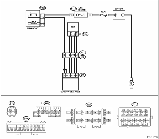
WIRING DIAGRAM:
Engine electrical system Engine Electrical System">
| STEP | CHECK | YES | NO |
1.CHECK POWER SUPPLY TO EGR CONTROL VALVE.
1) Turn the ignition switch to OFF.
2) Disconnect the connector from the EGR control valve.
3) Turn the ignition switch to ON.
4) Measure the voltage between EGR control valve connector and engine ground.
Connector & terminal
(E18) No. 2 (+) — Engine ground (−):
(E18) No. 5 (+) — Engine ground (−):
Is the voltage 10 V or more?
Diagnostic Procedure with Diagnostic Trouble Code (DTC) > DTC P1498 COIL 4 EGR "A" CONTROL CIRCUIT LOW">Go to Step 2.
Repair the harness and connector.
NOTE:
In this case, repair the following item:
• Open circuit in harness between EGR control valve and main relay connector
• Poor contact of coupling connector
2.CHECK HARNESS BETWEEN ECM AND EGR CONTROL VALVE CONNECTOR.
1) Turn the ignition switch to OFF.
2) Disconnect the connector from ECM.
3) Measure the resistance between ECM connector and EGR control valve connector.
Connector & terminal
DTC P1492; (B136) No. 11 — (E18) No. 3:
DTC P1494; (B136) No. 13 — (E18) No. 1:
DTC P1496; (B136) No. 31 — (E18) No. 4:
DTC P1498; (B136) No. 32 — (E18) No. 6:
Is the resistance less than 1 ??
Diagnostic Procedure with Diagnostic Trouble Code (DTC) > DTC P1498 COIL 4 EGR "A" CONTROL CIRCUIT LOW">Go to Step 3.
Repair the harness and connector.
NOTE:
In this case, repair the following item:
• Open circuit of harness between ECM connector and EGR control valve connector
• Poor contact of coupling connector
3.CHECK HARNESS BETWEEN ECM AND EGR CONTROL VALVE CONNECTOR.
1) Disconnect the connector from ECM.
2) Measure the resistance between ECM connector and chassis ground.
Connector & terminal
DTC P1492; (B136) No. 11 — Chassis ground:
DTC P1494; (B136) No. 13 — Chassis ground:
DTC P1496; (B136) No. 31 — Chassis ground:
DTC P1498; (B136) No. 32 — Chassis ground:
Is the resistance 1 M? or more?
Diagnostic Procedure with Diagnostic Trouble Code (DTC) > DTC P1498 COIL 4 EGR "A" CONTROL CIRCUIT LOW">Go to Step 4.
Repair ground short circuit of harness between ECM connector and EGR control valve connector.
4.CHECK FOR POOR CONTACT.
Check for poor contact between ECM connector and EGR control valve connector.
Is there poor contact in ECM or EGR control valve connector?
Repair the poor contact of ECM or EGR control valve connector.
Replace EGR control valve. EGR Control Valve">
1. OUTLINE OF DIAGNOSIS
NOTE:
For the detection standard, refer to DTC P1492. Diagnostic Procedure with Diagnostic Trouble Code (DTC) > DTC P1492 COIL 1 EGR "A" CONTROL CIRCUIT LOW">
 Dtc p1497 coil 3 egr "a" control circuit high
ENGINE (DIAGNOSTICS)(H4DO) > Diagnostic Procedure with Diagnostic Trouble Code (DTC)DTC P1497 COIL 3 EGR "A" CONTROL CIRCUIT HIGHNOTE:For the diagnostic procedure, refer to DTC P1499. Di ...
 Dtc p1499 coil 4 egr "a" control circuit high
ENGINE (DIAGNOSTICS)(H4DO) > Diagnostic Procedure with Diagnostic Trouble Code (DTC)DTC P1499 COIL 4 EGR "A" CONTROL CIRCUIT HIGHDTC detecting condition:Immediately at fault recognitionTr ...
Other materials:
Lock/unlock
The rear gate can be locked and unlocked
using any of the following systems
Power door locking switch: Refer to
"Power door locking switches" 2-8.
Keyless access with the push-button
start system (if equipped): Refer to "Keyless
access with push-button start system"
2-9.
...
Inspection
POWER ASSISTED SYSTEM (POWER STEERING) > Steering WheelINSPECTION1. PADDLE SHIFT SWITCHCheck the resistance of paddle switch.STEPCHECKYESNO1.SHIFT-UP SWITCH CONTINUITY CHECK.1) Operate the + side of paddle shift assembly and hold it.2) Measure the resistance between terminals of the paddle shift ...
Replacement
BRAKE > Brake FluidREPLACEMENTCAUTION:• Do not let brake fluid come into contact with the painted surface of the vehicle body. Wash away with water immediately and wipe off if it is spilled by accident.• Do not reuse drained brake fluid. When refilling brake fluid, always refill new b ...
