Subaru Crosstrek Service Manual: Dtc c2511 torque sensor main
POWER ASSISTED SYSTEM (POWER STEERING) (DIAGNOSTICS) > Diagnostic Procedure with Diagnostic Trouble Code (DTC)
DTC C2511 TORQUE SENSOR MAIN
Trouble symptom:
• The steering wheel operation feels heavy.
• STEERING warning light illuminates.
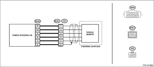
Wiring diagram:
Electric power steering system Electric Power Steering System">
| STEP | CHECK | YES | NO |
1.CHECK TORQUE SENSOR SIGNAL.
1) Display the current data of the power steering control module using the Subaru Select Monitor.
2) Check the voltage of «Torque sensor main output», «Torque sensor sub output», «Torque sensor reference voltage» and «Torque sensor power supply voltage».
Are the voltage of «Torque sensor main output» and «Torque sensor sub output» 2.5±0.1 V?
Is the voltage of «Torque sensor reference voltage» 3±0.1 V?
Is the voltage of «Torque sensor power supply voltage» 8±0.4 V?
Check for poor contact of the connector, and check the conditions again. If the condition recur, go to the next step. Diagnostic Procedure with Diagnostic Trouble Code (DTC) > DTC C2511 TORQUE SENSOR MAIN">Go to Step 2.
If it does not recur, complete the inspection.
Diagnostic Procedure with Diagnostic Trouble Code (DTC) > DTC C2511 TORQUE SENSOR MAIN">Go to Step 2.
2.CHECK HARNESS.
1) Turn the ignition switch to OFF.
2) Disconnect the connectors (B450, B451).
3) Using a tester and test harness, check the internal resistance of the harness terminals.
Connector & terminal
(B450) No. 4 — (B451) No. 3:
(B450) No. 5 — (B451) No. 5:
(B450) No. 8 — (B451) No. 1:
(B450) No. 9 — (B451) No. 2:
(B450) No. 10 — (B451) No. 4:
Is the resistance less than 10 ??
Diagnostic Procedure with Diagnostic Trouble Code (DTC) > DTC C2511 TORQUE SENSOR MAIN">Go to Step 3.
Repair or replace the harness.
3.CHECK POWER STEERING CONTROL MODULE.
1) Connect the connector (B450) to the power steering control module.
2) Turn the ignition switch to ON.
3) Short the circuit between connector (B451) terminals.
Terminals
No. 4 — No. 3:
No. 4 — No. 5:
4) Using the Subaru Select Monitor, check the voltages of «Torque sensor main output» and «Torque sensor sub output».
Are the voltages of «Torque sensor main output» and «Torque sensor sub output» before you short the circuit 0±0.1 V?
Are the voltages of «Torque sensor main output» and «Torque sensor sub output» after you short the circuit 3±0.1 V?
Replace the steering gearbox. Electric Power Steering Gearbox">
Replace the power steering control module. Power Steering Control Module">
 Dtc u0122 lost communication with vehicle dynamics control module
POWER ASSISTED SYSTEM (POWER STEERING) (DIAGNOSTICS) > Diagnostic Procedure with Diagnostic Trouble Code (DTC)DTC U0122 LOST COMMUNICATION WITH VEHICLE DYNAMICS CONTROL MODULENOTE:Refer to “L ...
 Dtc c2512 torque sensor sub
POWER ASSISTED SYSTEM (POWER STEERING) (DIAGNOSTICS) > Diagnostic Procedure with Diagnostic Trouble Code (DTC)DTC C2512 TORQUE SENSOR SUBNOTE:Refer to “DTC C2511 TORQUE SENSOR MAIN” for ...
Other materials:
Inspection
DRIVE SHAFT SYSTEM > Rear Drive ShaftINSPECTIONCheck the removed parts for damage, wear, corrosion etc. Repair or replace if defective.• DOJ (Double Offset Joint):Check for seizure, corrosion, damage, wear and excessive play.• BJ (Bell Joint):Check for seizure, corrosion, damage and e ...
Wheel alignment Inspection
REAR SUSPENSION > Wheel AlignmentINSPECTIONNOTE:Measure and adjust the front and rear wheel alignment at a time. Refer to “Wheel Alignment” in “FRONT SUSPENSION” section for measurement or adjustment of wheel alignment.• Inspection: Wheel Alignment > INSPECTION&q ...
Manual climate control operation for rear climate control
The Subaru Ascent allows rear passengers to adjust climate settings either through
the rear climate control panel or via the central information display.
To access rear climate control settings on the display, tap the rear climate
control mode indicator.
Locking and unlocking the rear climate ...
