Subaru Crosstrek Service Manual: Dtc p0030 a/f / o2 heater control circuit bank 1 sensor 1
ENGINE (DIAGNOSTICS)(H4DO) > Diagnostic Procedure with Diagnostic Trouble Code (DTC)
DTC P0030 A/F / O2 HEATER CONTROL CIRCUIT BANK 1 SENSOR 1
DTC detecting condition:
Detected when two consecutive driving cycles with fault occur.
CAUTION:
After servicing or replacing faulty parts, perform Clear Memory Mode Clear Memory Mode > OPERATION"> , and Inspection Mode Inspection Mode > PROCEDURE">.
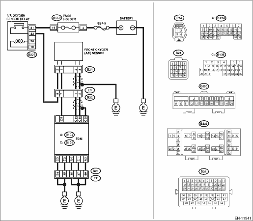
Wiring diagram:
Engine electrical system Engine Electrical System">
| STEP | CHECK | YES | NO |
1.CHECK HARNESS BETWEEN ECM AND FRONT OXYGEN (A/F) SENSOR CONNECTOR.
1) Start and warm up the engine.
2) Turn the ignition switch to OFF.
3) Disconnect the connector from ECM.
4) Disconnect the connectors from front oxygen (A/F) sensor.
5) Measure the resistance of harness between ECM connector and front oxygen (A/F) sensor connector.
Connector & terminal
(B136) No. 5 — (E24) No. 1:
(B136) No. 19 — (E24) No. 3:
(B136) No. 18 — (E24) No. 4:
Is the resistance less than 1 ??
Diagnostic Procedure with Diagnostic Trouble Code (DTC) > DTC P0030 A/F / O2 HEATER CONTROL CIRCUIT BANK 1 SENSOR 1">Go to Step 2.
Repair the harness and connector.
NOTE:
In this case, repair the following item:
• Open circuit in harness between ECM connector and front oxygen (A/F) sensor connector
• Poor contact of coupling connector
2.CHECK FRONT OXYGEN (A/F) SENSOR.
Measure the resistance between front oxygen (A/F) sensor terminals.
Terminals
No. 1 — No. 2:
Is the resistance 2 — 3 ??
Diagnostic Procedure with Diagnostic Trouble Code (DTC) > DTC P0030 A/F / O2 HEATER CONTROL CIRCUIT BANK 1 SENSOR 1">Go to Step 3.
Replace the front oxygen (A/F) sensor. Front Oxygen (A/F) Sensor">
3.CHECK FOR POOR CONTACT.
Check for poor contact of ECM and front oxygen (A/F) sensor connector.
Is there poor contact of ECM or front oxygen (A/F) sensor connector?
Repair the poor contact of ECM or front oxygen (A/F) sensor connector.
Replace the front oxygen (A/F) sensor. Front Oxygen (A/F) Sensor">
1. OUTLINE OF DIAGNOSIS
Detect functional errors of the front oxygen (A/F) sensor heater.
Judge as NG when it is determined that the front oxygen (A/F) sensor impedance is large when looking at engine status such as deceleration fuel cut.
2. COMPONENT DESCRIPTION
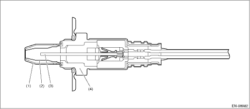
(1) | Element cover (outer) | (3) | Sensor element | (4) | Sensor housing |
(2) | Element cover (inner) |
3. EXECUTION CONDITION
Secondary parameters | Execution condition |
Battery voltage | ≥ 10.9 V |
A/F sensor heater control duty | > 17 % |
Elapsed time after fuel cut | ≥ 20000 ms |
4. GENERAL DRIVING CYCLE
Perform the diagnosis continuously after 42000 ms seconds or more have passed since the engine started.
5. DIAGNOSTIC METHOD
If the duration of time while the following conditions are met is longer than the time indicated, judge as NG.
Malfunction Criteria | Threshold Value |
Front oxygen (A/F) sensor impedance | > 82 ? |
Time Needed for Diagnosis: 10000 ms
Malfunction Indicator Light Illumination: Illuminates when malfunction occurs in 2 continuous driving cycles.
 Dtc p0024 "b" camshaft position - timing over-advanced or system performance bank 2
ENGINE (DIAGNOSTICS)(H4DO) > Diagnostic Procedure with Diagnostic Trouble Code (DTC)DTC P0024 "B" CAMSHAFT POSITION - TIMING OVER-ADVANCED OR SYSTEM PERFORMANCE BANK 2DTC detecting condit ...
 Dtc p0031 a/f / o2 heater control circuit low bank 1 sensor 1
ENGINE (DIAGNOSTICS)(H4DO) > Diagnostic Procedure with Diagnostic Trouble Code (DTC)DTC P0031 A/F / O2 HEATER CONTROL CIRCUIT LOW BANK 1 SENSOR 1DTC DETECTING CONDITION:Immediately at fault recogni ...
Other materials:
Installation
HVAC SYSTEM (HEATER, VENTILATOR AND A/C) > Heater DuctINSTALLATIONCAUTION:Before handling the airbag system components, refer to “CAUTION” of “General Description” in “AIRBAG SYSTEM”. General Description > CAUTION">Install each part in the reverse o ...
Note Note
NOTENOTEThis information will improve the efficiency of maintenance and assure the sound work.1. CLEANING• Perform the operation in a clean location and use extra caution in dust proofing.• Clean the items (except for assembly components) with steam, etc. before disassembly. During steam ...
General diagnostic table Inspection
ENGINE (DIAGNOSTICS)(H4DO) > General Diagnostic TableINSPECTION1. ENGINENOTE:Malfunction of parts other than those listed is also possible. Engine Trouble in General">SymptomsFaulty parts1. Engine stalls during idling.1) Manifold absolute pressure sensor2) Mass air flow and intake air te ...
