Subaru Crosstrek Service Manual: Dtc p0031 a/f / o2 heater control circuit low bank 1 sensor 1
ENGINE (DIAGNOSTICS)(H4DO) > Diagnostic Procedure with Diagnostic Trouble Code (DTC)
DTC P0031 A/F / O2 HEATER CONTROL CIRCUIT LOW BANK 1 SENSOR 1
DTC DETECTING CONDITION:
Immediately at fault recognition
CAUTION:
After servicing or replacing faulty parts, perform Clear Memory Mode Clear Memory Mode > OPERATION"> , and Inspection Mode Inspection Mode > PROCEDURE">.
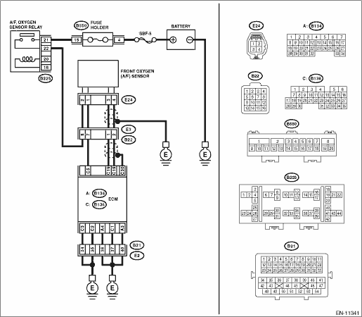
WIRING DIAGRAM:
Engine electrical system Engine Electrical System">
| STEP | CHECK | YES | NO |
1.CHECK POWER SUPPLY TO FRONT OXYGEN (A/F) SENSOR.
1) Turn the ignition switch to OFF.
2) Disconnect the connectors from front oxygen (A/F) sensor.
3) Turn the ignition switch to ON.
4) Measure the voltage between front oxygen (A/F) sensor connector and engine ground.
Connector & terminal
(E24) No. 2 (+) — Engine ground (−):
Is the voltage 10 V or more?
Diagnostic Procedure with Diagnostic Trouble Code (DTC) > DTC P0031 A/F / O2 HEATER CONTROL CIRCUIT LOW BANK 1 SENSOR 1">Go to Step 2.
Repair the power supply line.
NOTE:
In this case, repair the following item:
• Open circuit in harness between A/F, oxygen sensor relay connector and front oxygen (A/F) sensor connector
• Poor contact of A/F, oxygen sensor relay connector
• Poor contact of coupling connector
• Malfunction of A/F, oxygen sensor relay
2.CHECK HARNESS BETWEEN ECM AND FRONT OXYGEN (A/F) SENSOR CONNECTOR.
1) Turn the ignition switch to OFF.
2) Disconnect the connector from ECM.
3) Measure the resistance between ECM connector and front oxygen (A/F) sensor connector.
Connector & terminal
(B136) No. 5 — (E24) No. 1:
Is the resistance less than 1 ??
Diagnostic Procedure with Diagnostic Trouble Code (DTC) > DTC P0031 A/F / O2 HEATER CONTROL CIRCUIT LOW BANK 1 SENSOR 1">Go to Step 3.
Repair the harness and connector.
NOTE:
In this case, repair the following item:
• Open circuit in harness between ECM connector and front oxygen (A/F) sensor connector
• Poor contact of coupling connector
3.CHECK GROUND CIRCUIT FOR ECM.
Measure the resistance of harness between ECM connector and chassis ground.
Connector & terminal
(B134) No. 3 — Chassis ground:
(B134) No. 4 — Chassis ground:
(B136) No. 1 — Chassis ground:
(B136) No. 2 — Chassis ground:
(B136) No. 3 — Chassis ground:
Is the resistance less than 5 ??
Diagnostic Procedure with Diagnostic Trouble Code (DTC) > DTC P0031 A/F / O2 HEATER CONTROL CIRCUIT LOW BANK 1 SENSOR 1">Go to Step 4.
Repair the harness and connector.
NOTE:
In this case, repair the following item:
• Open circuit of harness between ECM connector and engine ground
• Poor contact of coupling connector
4.CHECK FRONT OXYGEN (A/F) SENSOR.
Measure the resistance between front oxygen (A/F) sensor terminals.
Terminals
No. 1 — No. 2:
Is the resistance 2 — 3 ??
Repair the poor contact of ECM connector.
Replace the front oxygen (A/F) sensor. Front Oxygen (A/F) Sensor">
1. OUTLINE OF DIAGNOSIS
Detect front oxygen (A/F) sensor heater open or short circuit.
The front oxygen (A/F) sensor heater performs duty control, and the output terminal voltage at ON is 0 V, and the output terminal voltage at OFF is the battery voltage.
Judge as NG when the terminal voltage remains Low.
2. COMPONENT DESCRIPTION
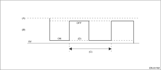
(A) | Battery voltage | (B) | Front oxygen (A/F) sensor heater output voltage | (C) | 128 ms |
(D) | Low error |
3. EXECUTION CONDITION
Secondary Parameters | Execution condition |
Battery voltage | ≥ 10.9 V |
Primary oxygen sensor heater control duty | < 87.5 % |
4. GENERAL DRIVING CYCLE
Always perform the diagnosis continuously.
5. DIAGNOSTIC METHOD
If the duration of time while the following conditions are met is longer than the time indicated, judge as NG.
Malfunction Criteria | Threshold Value |
Measured primary oxygen sensor heater control voltage | < 1.9 V |
Time Needed for Diagnosis: 1 second
Malfunction Indicator Light Illumination: Illuminates as soon as a malfunction occurs.
 Dtc p0030 a/f / o2 heater control circuit bank 1 sensor 1
ENGINE (DIAGNOSTICS)(H4DO) > Diagnostic Procedure with Diagnostic Trouble Code (DTC)DTC P0030 A/F / O2 HEATER CONTROL CIRCUIT BANK 1 SENSOR 1DTC detecting condition:Detected when two consecutive dr ...
 Dtc p0032 a/f / o2 heater control circuit high bank 1 sensor 1
ENGINE (DIAGNOSTICS)(H4DO) > Diagnostic Procedure with Diagnostic Trouble Code (DTC)DTC P0032 A/F / O2 HEATER CONTROL CIRCUIT HIGH BANK 1 SENSOR 1DTC DETECTING CONDITION:Immediately at fault recogn ...
Other materials:
Dtc b1572 imm circuit except antenna circuit
IMMOBILIZER (DIAGNOSTICS) > Diagnostic Procedure with Diagnostic Trouble Code (DTC)DTC B1572 IMM CIRCUIT EXCEPT ANTENNA CIRCUITDTC detecting condition:Communication failure between body integrated unit and ECMCAUTION:When the body integrated unit is replaced, registration of the immobilizer syste ...
Removal
EXHAUST(H4DO) > Front Exhaust PipeREMOVALCAUTION:Vehicle components are extremely hot after driving. Be wary of receiving burns from heated parts.1. Disconnect the ground cable from battery. NOTE">2. Lift up the vehicle.3. Remove the under cover. Front Under Cover > REMOVAL"> ...
How to contact the vehicle manufacturer concerning modifications for persons
with disabilities that may affect the advanced airbag system
Any modifications to the Subaru Ascent—especially those involving seats, seatbelts,
front structure, steering components, suspension, or floor panels—may directly impact
the operation of the advanced airbag system. This is particularly important when
adapting the vehicle for drivers or pas ...
