Subaru Crosstrek Service Manual: Dtc p0032 a/f / o2 heater control circuit high bank 1 sensor 1
ENGINE (DIAGNOSTICS)(H4DO) > Diagnostic Procedure with Diagnostic Trouble Code (DTC)
DTC P0032 A/F / O2 HEATER CONTROL CIRCUIT HIGH BANK 1 SENSOR 1
DTC DETECTING CONDITION:
Immediately at fault recognition
CAUTION:
After servicing or replacing faulty parts, perform Clear Memory Mode Clear Memory Mode > OPERATION"> , and Inspection Mode Inspection Mode > PROCEDURE">.
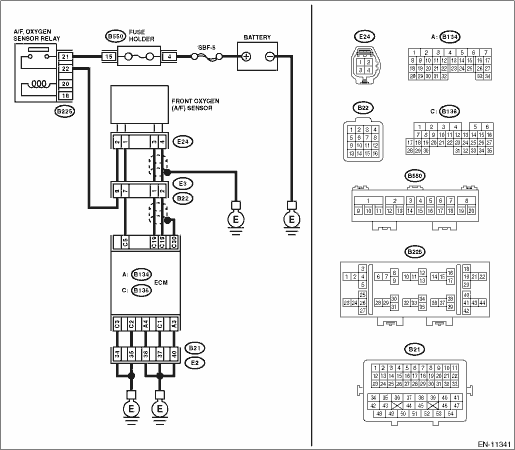
WIRING DIAGRAM:
Engine electrical system Engine Electrical System">
| STEP | CHECK | YES | NO |
1.CHECK HARNESS BETWEEN ECM AND FRONT OXYGEN (A/F) SENSOR CONNECTOR.
1) Turn the ignition switch to OFF.
2) Measure the voltage between ECM connector and chassis ground.
Connector & terminal
(B136) No. 5 (+) — Chassis ground (−):
Is the voltage 10 V or more?
Repair the short circuit to power in the harness between ECM connector and front oxygen (A/F) sensor connector.
Diagnostic Procedure with Diagnostic Trouble Code (DTC) > DTC P0032 A/F / O2 HEATER CONTROL CIRCUIT HIGH BANK 1 SENSOR 1">Go to Step 2.
2.CHECK GROUND CIRCUIT FOR ECM.
1) Disconnect the connector from ECM.
2) Measure the resistance between ECM connector and chassis ground.
Connector & terminal
(B134) No. 3 — Chassis ground:
(B134) No. 4 — Chassis ground:
(B136) No. 1 — Chassis ground:
(B136) No. 2 — Chassis ground:
(B136) No. 3 — Chassis ground:
Is the resistance less than 5 ??
Repair the poor contact of ECM connector.
Repair the harness and connector.
NOTE:
In this case, repair the following item:
• Open circuit of harness between ECM connector and engine ground
• Poor contact of coupling connector
1. OUTLINE OF DIAGNOSIS
Detect front oxygen (A/F) sensor heater open or short circuit.
The front oxygen (A/F) sensor heater performs duty control, and the output terminal voltage at ON is 0 V, and the output terminal voltage at OFF is the battery voltage.
Judge as NG when the terminal voltage remains High.
2. COMPONENT DESCRIPTION
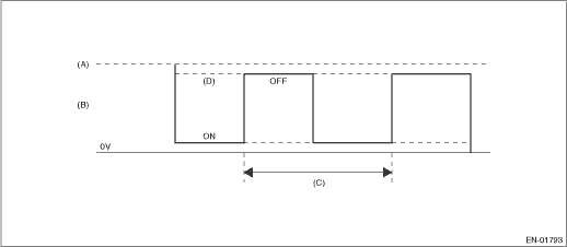
(A) | Battery voltage | (B) | Front oxygen (A/F) sensor heater output voltage | (C) | 128 ms |
(D) | High error |
3. EXECUTION CONDITION
Secondary Parameters | Execution condition |
Battery voltage | ≥ 10.9 V |
Primary oxygen sensor heater control duty | > 12.5 % |
4. GENERAL DRIVING CYCLE
Always perform the diagnosis continuously.
5. DIAGNOSTIC METHOD
If the duration of time while the following conditions are met is longer than the time indicated, judge as NG.
Malfunction Criteria | Threshold Value |
Measured primary oxygen sensor heater control voltage | ≥ 1.9 V |
Time Needed for Diagnosis: 2 seconds
Malfunction Indicator Light Illumination: Illuminates as soon as a malfunction occurs.
 Dtc p0031 a/f / o2 heater control circuit low bank 1 sensor 1
ENGINE (DIAGNOSTICS)(H4DO) > Diagnostic Procedure with Diagnostic Trouble Code (DTC)DTC P0031 A/F / O2 HEATER CONTROL CIRCUIT LOW BANK 1 SENSOR 1DTC DETECTING CONDITION:Immediately at fault recogni ...
 Dtc p0037 a/f / o2 heater control circuit low bank 1 sensor 2
ENGINE (DIAGNOSTICS)(H4DO) > Diagnostic Procedure with Diagnostic Trouble Code (DTC)DTC P0037 A/F / O2 HEATER CONTROL CIRCUIT LOW BANK 1 SENSOR 2DTC DETECTING CONDITION:Detected when two consecutiv ...
Other materials:
Removal
MANUAL TRANSMISSION AND DIFFERENTIAL(5MT) > Air Breather HoseREMOVAL1. Disconnect the ground cable from battery.2. Remove the clip (A) from the air intake boot.3. Loosen the clamp (B) connecting the air intake boot and air cleaner case (rear).4. Loosen the clamp (C) which connects the air intake ...
Dtc p2404 evap system leak detection pump sense circuit range/performance
ENGINE (DIAGNOSTICS)(H4DO) > Diagnostic Procedure with Diagnostic Trouble Code (DTC)DTC P2404 EVAP SYSTEM LEAK DETECTION PUMP SENSE CIRCUIT RANGE/PERFORMANCEDTC detecting condition:Detected when two consecutive driving cycles with fault occur.CAUTION:After servicing or replacing faulty parts, per ...
Dtc c0054 bls off malfunction
VEHICLE DYNAMICS CONTROL (VDC) (DIAGNOSTICS) > Diagnostic Procedure with Diagnostic Trouble Code (DTC)DTC C0054 BLS OFF MALFUNCTIONDTC detecting condition:Defective stop light switchTrouble symptom:• VDC does not operate.• EyeSight does not operate.Wiring diagram:Vehicle dynamics cont ...
