Subaru Crosstrek Service Manual: Dtc p015a a/f / o2 sensor delayed response - rich to lean bank 1 sensor 1
ENGINE (DIAGNOSTICS)(H4DO) > Diagnostic Procedure with Diagnostic Trouble Code (DTC)
DTC P015A A/F / O2 SENSOR DELAYED RESPONSE - RICH TO LEAN BANK 1 SENSOR 1
NOTE:
For the diagnostic procedure, refer to DTC P014C. Diagnostic Procedure with Diagnostic Trouble Code (DTC) > DTC P014C A/F / O2 SENSOR SLOW RESPONSE - RICH TO LEAN BANK 1 SENSOR 1">
1. OUTLINE OF DIAGNOSIS
Detect the slow response of front oxygen (A/F) sensor.
For diagnosis, detect the trouble by processing the λ waveform in normal driving without forcibly changing the target air fuel ratio.
2. COMPONENT DESCRIPTION
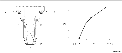
(A) | Electromotive force | (B) | Air fuel ratio | (C) | Rich |
(D) | Lean | ||||
(1) | Exhaust gas | (2) | Zirconia element oxygen |
3. EXECUTION CONDITION
Secondary parameters | Execution condition |
Battery voltage | ≥ 10.9 V |
Barometric pressure | > 75.1 kPa (563 mmHg, 22.2 inHg) |
Duration of main feedback | ≥ 3000 ms |
Engine speed | ≥ 1000 rpm |
Amount of intake air | ≥ 10 g/s (0.35 oz/s) (CVT model) ≥ 10 g/s (0.35 oz/s) (MT model) |
Secondary parameters | Execution condition |
Battery voltage | ≥ 10.9 V |
Barometric pressure | ≥ 75.1 kPa (563 mmHg, 22.2 inHg) |
Main feedback | In operation |
Vehicle speed | > 40 km/h (24.9 MPH) |
Engine speed | ≥ 1000 rpm and < 4000 rpm |
Amount of intake air | ≥ 7.5 g/s (0.26 oz/s) and < 40 g/s (1.41 oz/s) |
Catalyst depletion diagnosis | Not under diagnosis |
4. GENERAL DRIVING CYCLE
Perform diagnosis only once in a city driving including normal acceleration and deceleration.
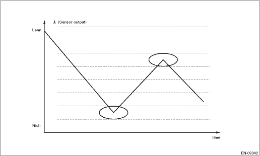
5. DIAGNOSTIC METHOD 1
Detect the malfunction depending on the average value of time necessary for λ to inverse the air fuel ratio from “Lean > Rich > Lean” to “Rich > Lean > Rich”.
Judge as NG when the following conditions are established.
Diagnosis (CVT model)
Malfunction Criteria | Threshold Value | DTC |
Average value of time necessary for λ to inverse the air fuel ratio to Lean > Rich > Lean | > 100 ms | P015A |
and | ||
Average value of time needed to change to Lean | > 130 ms | |
Average value of time necessary for λ to inverse the air fuel ratio to Rich > Lean > Rich | > 200 ms | P015B |
and | ||
Average value of time needed to change to Rich | > 300 ms |
Diagnosis (MT model)
Malfunction Criteria | Threshold Value | DTC |
Average value of time necessary for λ to inverse the air fuel ratio to Lean > Rich > Lean | > 120 ms | P015A |
and | ||
Average value of time needed to change to Lean | > 150 ms | |
Average value of time necessary for λ to inverse the air fuel ratio to Rich > Lean > Rich | > 200 ms | P015B |
and | ||
Average value of time needed to change to Rich | > 250 ms |
Diagnosis (CVT model)
Time Needed for Diagnosis: 90 seconds
Diagnosis (MT model)
Time Needed for Diagnosis: 60 seconds
Malfunction Indicator Light Illumination: Illuminates when malfunction occurs in 2 continuous driving cycles.
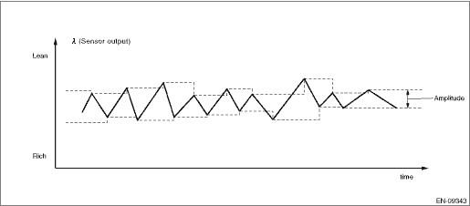
6. DIAGNOSTIC METHOD 2
Detect the malfunction by calculating the average amplitude of λ.
Judge as NG when the following conditions are established.
Malfunction Criteria | Threshold Value | DTC |
Average value for λ amplitude | > 0.07 | P015A and P015B |
Time needed for diagnosis: 1000 ms ? 4.5 ms
Malfunction indicator light illumination: Illuminates when malfunction occurs in 2 continuous driving cycles.
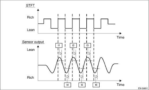
7. DIAGNOSIS METHOD 3 (MT MODEL ONLY)
Change STFT (A/F compensation value) by interruption, and measure the reaction time of λ value. When A/F sensor malfunctions, the reaction time takes longer than at normal condition. In this case, judge as abnormal.
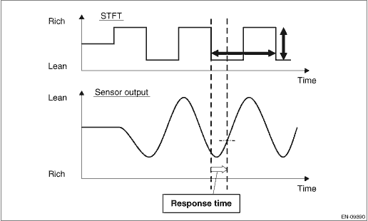
Measure reaction time (t1, t2, t3) and reaction time (t4, t5, t6). Use the average value of the reaction time to obtain the diagnostic value.
Judge as NG when the following conditions are established.
Malfunction Criteria | Threshold Value | DTC |
Condition either A or B should be satisfied. | ||
A: | P015A and P015B | |
Average value for λ amplitude | > 0.1 | |
or | ||
B: | ||
(t1 + t2 + t3)/3 | > 450 ms | |
and | ||
(t4 + t5 + t6)/3 | > 450 ms |
Time Needed for Diagnosis: 1000 ms ? 4.5 ms
Malfunction Indicator Light Illumination: Illuminates when malfunction occurs in 2 continuous driving cycles.
 Dtc p014d a/f / o2 sensor slow response - lean to rich bank 1 sensor 1
ENGINE (DIAGNOSTICS)(H4DO) > Diagnostic Procedure with Diagnostic Trouble Code (DTC)DTC P014D A/F / O2 SENSOR SLOW RESPONSE - LEAN TO RICH BANK 1 SENSOR 1NOTE:For the diagnostic procedure, refer to ...
 Dtc p015b a/f / o2 sensor delayed response - lean to rich bank 1 sensor 1
ENGINE (DIAGNOSTICS)(H4DO) > Diagnostic Procedure with Diagnostic Trouble Code (DTC)DTC P015B A/F / O2 SENSOR DELAYED RESPONSE - LEAN TO RICH BANK 1 SENSOR 1NOTE:For the diagnostic procedure, refer ...
Other materials:
Removal
EXTERIOR BODY PANELS > Rear DoorREMOVAL1. REAR DOOR PANEL1. Disconnect the ground cable from battery. NOTE">2. Remove the trim panel - rear door. Door Trim > REMOVAL">3. Remove the sealing cover - rear door. Rear Sealing Cover > REMOVAL">4. Remove the cover B pill ...
Removal
HVAC SYSTEM (HEATER, VENTILATOR AND A/C) > Blower Motor Unit AssemblyREMOVALCAUTION:Before handling the airbag system components, refer to “CAUTION” of “General Description” in “AIRBAG SYSTEM”. General Description > CAUTION">1. Disconnect the ground ...
Type C and D
1. Depress the "AUTO" button. The
indicator light "FULL AUTO" on the display
illuminates.
2. Set the preferred temperature using
the temperature control dial.
NOTE
The controllable temperature range
may vary depending on the regional
specifications of the vehicle.
If you operate any ...
