
Subaru Crosstrek Service Manual: Dtc c2532 control module peripheral circuit
POWER ASSISTED SYSTEM (POWER STEERING) (DIAGNOSTICS) > Diagnostic Procedure with Diagnostic Trouble Code (DTC)
DTC C2532 CONTROL MODULE PERIPHERAL CIRCUIT
TROUBLE SYMPTOM:
• The steering wheel operation feels heavy.
• STEERING warning light illuminates.
WIRING DIAGRAM:
Electric power steering system Electric Power Steering System">
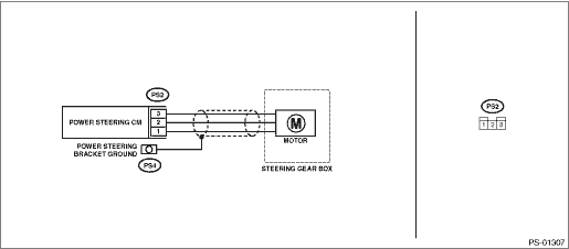
| STEP | CHECK | YES | NO |
1.CHECK CONNECTOR.
Check the connection status of the power steering control module and motor harness (PS2).
Is the connector firmly installed?
Diagnostic Procedure with Diagnostic Trouble Code (DTC) > DTC C2532 CONTROL MODULE PERIPHERAL CIRCUIT">Go to Step 2.
Install the connector, and check again.
2.CHECK CONNECTOR.
Check the appearance at connection of the power steering control module and motor harness (PS2).
Is the motor harness grommet coming out from the connector?
Replace the steering gearbox. Electric Power Steering Gearbox">
Diagnostic Procedure with Diagnostic Trouble Code (DTC) > DTC C2532 CONTROL MODULE PERIPHERAL CIRCUIT">Go to Step 3.
3.CHECK MOTOR UNIT.
1) Turn the ignition switch to OFF.
2) Disconnect the connector (PS2) from the power steering control module.
3) Use a tester to check for continuity in the motor.
Connector & terminal
(PS2) No. 1 — No. 2:
(PS2) No. 1 — No. 3:
(PS2) No. 2 — No. 3:
Is there continuity? (While shaking the harness)
Diagnostic Procedure with Diagnostic Trouble Code (DTC) > DTC C2532 CONTROL MODULE PERIPHERAL CIRCUIT">Go to Step 4.
Replace the steering gearbox. Electric Power Steering Gearbox">
4.CHECK MOTOR INSULATION.
Use a tester to check for short circuits in the motor.
Connector & terminal
(PS2) No. 1 — Steering gearbox body:
(PS2) No. 2 — Steering gearbox body:
(PS2) No. 3 — Steering gearbox body:
Is the resistance 1 M? or more? (While shaking the harness)
Replace the power steering control module. Power Steering Control Module">
Replace the steering gearbox. Electric Power Steering Gearbox">
 Dtc c2531 control module cpu
POWER ASSISTED SYSTEM (POWER STEERING) (DIAGNOSTICS) > Diagnostic Procedure with Diagnostic Trouble Code (DTC)DTC C2531 CONTROL MODULE CPUTROUBLE SYMPTOM:• The steering wheel operation feels ...
 Dtc c2533 control module board temperature sensor
POWER ASSISTED SYSTEM (POWER STEERING) (DIAGNOSTICS) > Diagnostic Procedure with Diagnostic Trouble Code (DTC)DTC C2533 CONTROL MODULE BOARD TEMPERATURE SENSORTROUBLE SYMPTOM:The steering wheel ope ...
Other materials:
Installation of child restraint systems by use of lower and tether anchorages
(LATCH)
The Subaru Ascent is equipped with a modern LATCH (Lower Anchors and Tethers
for Children) system, designed to simplify the installation of child restraint systems
while ensuring maximum safety. Using the LATCH system in the Subaru Ascent allows
secure attachment without relying solely on seat ...
Installation
CONTINUOUSLY VARIABLE TRANSMISSION(TR580) > CVTF Cooler (With Warmer Function)INSTALLATION1. Install the CVTF cooler (with warmer feature) to the transmission.Tightening torque:23 N·m (2.3 kgf-m, 17.0 ft-lb)2. Install the engine coolant inlet hose.NOTE:With the triangle mark on the engine ...
Dtc c1731 g sensor abnormal
VEHICLE DYNAMICS CONTROL (VDC) (DIAGNOSTICS) > Diagnostic Procedure with Diagnostic Trouble Code (DTC)DTC C1731 G SENSOR ABNORMALNOTE:For the diagnostic procedure, refer to “DTC C1732 LATERAL G SENSOR”. Diagnostic Procedure with Diagnostic Trouble Code (DTC) > DTC C1732 LATERAL G ...
