Subaru Crosstrek Service Manual: Dtc b27a7 trunk/rear gate internal antenna open
KEYLESS ACCESS WITH PUSH BUTTON START SYSTEM (DIAGNOSTICS) > Diagnostic Procedure with Diagnostic Trouble Code (DTC)
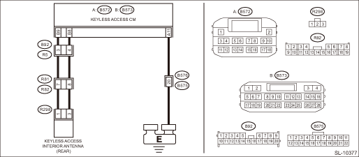
DTC B27A7 TRUNK/REAR GATE INTERNAL ANTENNA OPEN
DTC detecting condition:
When open circuit occurs in the harness between keyless access CM and rear interior antenna.
Trouble symptom:
Keyless access system does not function. (When the access key is in the rear area of the passenger room (within luggage compartment))
CAUTION:
For replacement procedure of keyless access CM, refer to the “REGISTRATION MANUAL FOR IMMOBILIZER” provided as a separate volume.
Wiring diagram:
Keyless access system Keyless Access System > WIRING DIAGRAM">
| STEP | CHECK | YES | NO |
1.CHECK LAN SYSTEM.
Inspect LAN system. Basic Diagnostic Procedure > PROCEDURE">
Is LAN system normal?
Diagnostic Procedure with Diagnostic Trouble Code (DTC) > DTC B27A7 TRUNK/REAR GATE INTERNAL ANTENNA OPEN">Go to Step 2.
Perform the inspection according to the diagnosis for LAN system.
2.CHECK CONNECTOR.
1) Disconnect the keyless access CM connector.
2) Disconnect the rear interior antenna connector.
Is the connector OK?
Diagnostic Procedure with Diagnostic Trouble Code (DTC) > DTC B27A7 TRUNK/REAR GATE INTERNAL ANTENNA OPEN">Go to Step 3.
Repair or replace the connector.
3.CHECK HARNESS (OPEN CIRCUIT).
Using a tester, measure the resistance between the keyless access CM connector and rear interior antenna connector, and between rear interior antenna connector, keyless access CM connector and chassis ground.
Connector & terminal
(B573) No. 9 — (R298) No. 1:
(B573) No. 8 — (R298) No. 3:
(B572) No. 11 — Chassis ground:
Is the resistance less than 1 ??
Diagnostic Procedure with Diagnostic Trouble Code (DTC) > DTC B27A7 TRUNK/REAR GATE INTERNAL ANTENNA OPEN">Go to Step 4.
Repair or replace the open circuit of harness.
4.CHECK HARNESS (GROUND SHORT CIRCUIT).
Using a tester, measure the resistance between the keyless access CM connector and chassis ground.
Connector & terminal
(B573) No. 9 — Chassis ground:
(B573) No. 8 — Chassis ground:
Is the resistance 10 k? or more?
Diagnostic Procedure with Diagnostic Trouble Code (DTC) > DTC B27A7 TRUNK/REAR GATE INTERNAL ANTENNA OPEN">Go to Step 5.
Repair or replace the short circuit of the harness.
5.CHECK DTC.
1) Connect the keyless access CM connector.
2) Using the Subaru Select Monitor, clear the memory. Clear Memory Mode">
3) Read DTC using the Subaru Select Monitor. Read Diagnostic Trouble Code (DTC)">
Is DTC B27A7 displayed?
Diagnostic Procedure with Diagnostic Trouble Code (DTC) > DTC B27A7 TRUNK/REAR GATE INTERNAL ANTENNA OPEN">Go to Step 6.
Even if DTC is displayed, the circuit has returned to a normal condition at this time. Reproduce the failure, and then perform the diagnosis again.
NOTE:
In this case, temporary poor contact of connector, temporary open or short circuit of harness may be the cause.
6.CHECK REAR INTERIOR ANTENNA.
1) Replace the rear interior antenna with the front interior antenna. Keyless Access Indoor Antenna">
2) Using the Subaru Select Monitor, clear the memory. Clear Memory Mode">
3) Read the DTC using Subaru Select Monitor. Read Diagnostic Trouble Code (DTC)">
Is DTC B27A7 displayed?
Replace the keyless access CM. Keyless Access CM">
Malfunction occurred in the rear interior antenna.
 Dtc b27a5 front internal antenna open
KEYLESS ACCESS WITH PUSH BUTTON START SYSTEM (DIAGNOSTICS) > Diagnostic Procedure with Diagnostic Trouble Code (DTC)DTC B27A5 FRONT INTERNAL ANTENNA OPENDTC detecting condition:When open circuit oc ...
 Dtc b27a8 trunk/rear gate external antenna open
KEYLESS ACCESS WITH PUSH BUTTON START SYSTEM (DIAGNOSTICS) > Diagnostic Procedure with Diagnostic Trouble Code (DTC)DTC B27A8 TRUNK/REAR GATE EXTERNAL ANTENNA OPENDTC detecting condition:When open ...
Other materials:
Surround View Monitor
The Subaru Ascent is equipped with a Surround View Monitor system that provides
a comprehensive visual overview of the vehicle’s surroundings. This system displays
real-time camera images on the center information display, helping the driver monitor
blind spots and improve situational awaren ...
Dtc p0717 input/turbine shaft speed sensor "a" circuit no signal
CONTINUOUSLY VARIABLE TRANSMISSION (DIAGNOSTICS) > Diagnostic Procedure with Diagnostic Trouble Code (DTC)DTC P0717 INPUT/TURBINE SHAFT SPEED SENSOR "A" CIRCUIT NO SIGNALDTC detecting condition:Immediately at fault recognitionTrouble symptom:• Standing start problems• Shock ...
Installation
POWER ASSISTED SYSTEM (POWER STEERING) > Steering ColumnINSTALLATIONCAUTION:If the steering wheel and steering angle sensor are removed, perform the following VDC setting mode.– Model without EyeSight: VDC sensor midpoint setting mode VDC Control Module and Hydraulic Control Unit (VDCCM&H ...
