
Subaru Crosstrek Service Manual: Disassembly
MANUAL TRANSMISSION AND DIFFERENTIAL(5MT) > Front Differential Assembly
DISASSEMBLY
1. DIFFERENTIAL CASE ASSEMBLY
1. Remove the twelve bolts and remove hypoid driven gear.

(A) | Hypoid driven gear |
2. Drive out the straight pin from differential assembly toward hypoid driven gear side.
| ST 899904100 | STRAIGHT PIN REMOVER |
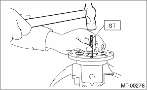
3. Pull out the pinion shaft, and remove the differential bevel pinion, differential bevel gear and adjusting washer.
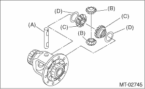
(A) | Pinion shaft |
(B) | Differential bevel pinion |
(C) | Differential bevel gear |
(D) | Adjusting washer |
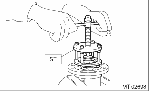
4. Using the ST, remove the taper roller bearing.
| ST 899524100 | PULLER SET |
2. DIFFERENTIAL SIDE RETAINER
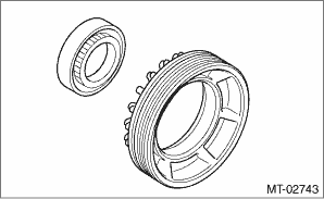
1. Remove the O-ring.
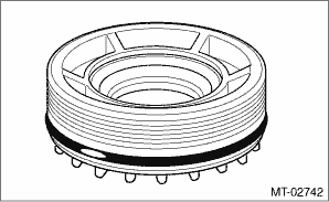
2. Remove the oil seal.
NOTE:
Remove it using a flat tip screwdriver wrapped with cloth or tape, etc.
 Assembly
MANUAL TRANSMISSION AND DIFFERENTIAL(5MT) > Front Differential AssemblyASSEMBLY1. DIFFERENTIAL CASE ASSEMBLY1. Install the differential bevel gear and differential bevel pinion together with adjust ...
 Inspection
MANUAL TRANSMISSION AND DIFFERENTIAL(5MT) > Front Differential AssemblyINSPECTIONRepair or replace the differential gear in the following cases:• When the hypoid driven gear and drive pinion ...
Other materials:
Dtc b28b6 pre-collision off switch
EyeSight (DIAGNOSTICS) > Diagnostic Procedure with Diagnostic Trouble Code (DTC)DTC B28B6 PRE-COLLISION OFF SWITCHDetected when pre-collision brake OFF switch circuit is not installed, open-circuited or is stuck to ON.DTC detecting condition:• Wiring of pre-collision brake OFF switch is not ...
Installation
CLUTCH SYSTEM > Clutch Disc and CoverINSTALLATION1. Insert the ST into the clutch disc and the ST end into pilot bearing to install the clutch disc.NOTE:When installing the clutch disc, be careful to attach in the correct direction.ST 499747100CLUTCH DISC GUIDE(A)Flywheel side2. Install the cl ...
Service mode (models without "keyless access with push-button start system")
In service mode, the remote engine start
function is temporarily disabled to prevent
the system from unexpectedly starting the
engine while being serviced.
To engage or disengage service mode:
1. Enter the vehicle and close all vehicle
doors and the rear gate.
2. Verify that the select le ...
