Subaru Crosstrek Service Manual: Diagnostic procedure for subaru select monitor communication Communication for initializing impossible
ENGINE (DIAGNOSTICS)(H4DO) > Diagnostic Procedure for Subaru Select Monitor Communication
COMMUNICATION FOR INITIALIZING IMPOSSIBLE
DIAGNOSIS:
Open or short circuit in data link connector
TROUBLE SYMPTOM:
Subaru Select Monitor communication failure
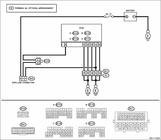
WIRING DIAGRAM:
Engine electrical system Engine Electrical System">
| STEP | CHECK | YES | NO |
1.CHECK POWER SUPPLY CIRCUIT.
Connect DST-i or general scan tool to data link connector.
Does DST-i or the general scan tool turn ON?
Diagnostic Procedure for Subaru Select Monitor Communication > COMMUNICATION FOR INITIALIZING IMPOSSIBLE">Go to Step 4.
Diagnostic Procedure for Subaru Select Monitor Communication > COMMUNICATION FOR INITIALIZING IMPOSSIBLE">Go to Step 2.
2.CHECK POWER SUPPLY CIRCUIT.
Measure the voltage between data link connector and chassis ground.
Connector & terminal
(B40) No. 16 (+) — Chassis ground (−):
Is the voltage 10 V or more?
Diagnostic Procedure for Subaru Select Monitor Communication > COMMUNICATION FOR INITIALIZING IMPOSSIBLE">Go to Step 3.
Repair the power supply circuit.
NOTE:
In this case, repair the following item:
• Open or ground short circuit of harness between battery and data link connector
• Blown out of fuse (M/B No. 13)
3.CHECK HARNESS BETWEEN DATA LINK CONNECTOR AND CHASSIS GROUND.
1) Turn the ignition switch to OFF.
2) Measure the resistance of harness between data link connector and chassis ground.
Connector & terminal
(B40) No. 4 — Chassis ground:
(B40) No. 5 — Chassis ground:
Is the resistance less than 5 ??
Repair the poor contact of data link connector.
Repair the harness and connector.
NOTE:
In this case, repair the following item:
• Open circuit in harness between ECM connector and data link connector
• Open circuit of harness between ECM connector and engine ground
• Poor contact of ECM connector
• Poor contact of coupling connector
4.CHECK HARNESS BETWEEN ECM AND DATA LINK CONNECTOR.
Measure the resistance between data link connector and chassis ground.
Connector & terminal
(B40) No. 7 — Chassis ground:
Is the resistance 1 M? or more?
Repair the poor contact of the ECM or data link connector.
Repair the short circuit to ground in harness between ECM connector and data link connector.
 Data link connector Note
ENGINE (DIAGNOSTICS)(H4DO) > Data Link ConnectorNOTEThis connector is used for Subaru Select Monitor.CAUTION:Do not connect any scan tools other than Subaru Select Monitor or general scan tool beca ...
 Drive cycle Procedure
ENGINE (DIAGNOSTICS)(H4DO) > Drive CyclePROCEDUREIt is necessary to perform the drive cycle listed below if DTC is not found in the Inspection Mode. It is possible to complete diagnosis of the DTC ...
Other materials:
Using aha application
1. When the top screen is displayed,
touch the station key.
Example of the main screen
2. Select the desired station from the list.
The selected station is displayed.
NOTE
The following operations are not
available on this system. Perform these
operations on the smartphone.
Add ...
Component
STARTING/CHARGING SYSTEMS(H4DO) > General DescriptionCOMPONENT1. STARTER(1)Starter housing ASSY(9)Overrunning clutch(17)Sleeve bearing(2)Sleeve bearing(10)Internal gear ASSY(18)Starter cover ASSY(3)Shift lever(11)Shaft (4)Plate(12)Pinion gearTightening torque: N·m (kgf-m, ft-lb)(5)Seal rub ...
Preparation for date setting
Turn the ignition switch to the "ON"
position.
Push and hold the button to show
the selection screen.
After the selection screen is displayed,
operate the "
"
or "
" switch to show the
"Time/Date" item. Then, push the
button.
...
