Subaru Crosstrek Service Manual: Disassembly
GLASS/WINDOWS/MIRRORS > Outer Mirror Assembly
DISASSEMBLY
CAUTION:
When removing the mirror - repair, be careful not to damage the back surface of mirror - repair with a flat tip screwdriver.
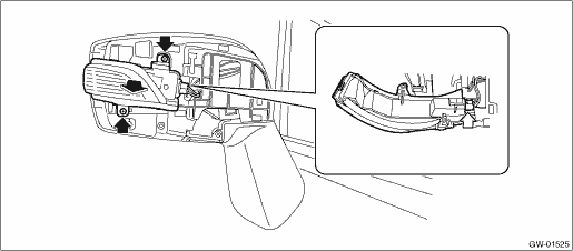
1. Operate the remote control mirror switch to face the mirror - repair upward.
2. Disconnect the ground cable from battery and wait for at least 60 seconds before starting work. NOTE">
3. Remove the mirror - repair.
(1) Using a flat tip screwdriver, release the clip, and slide the mirror - repair downward to remove.
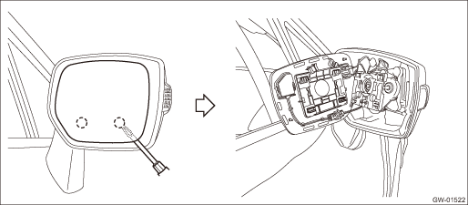
(2) Disconnect connectors. (Model with mirror heater and Subaru Rear Vehicle Detection system)
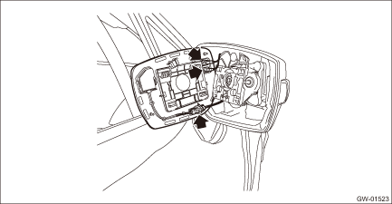
4. Release the claws, and then remove the cover - cap outer mirror lower.
5. Release the claws, and then remove the cover - cap outer mirror.
CAUTION:
Be careful not to apply excessive force when removing the cover - cap outer mirror, as the lower hooks may become damaged.
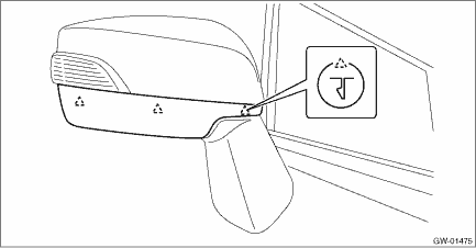
6. Remove the light assembly - side turn mirror. (Model with side turn signal light)
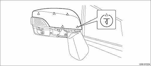
(1) Remove the screws and pull out the light assembly - side turn mirror to the front of the vehicle.
(2) Disconnect the connector and remove the light assembly - side turn mirror.
 Removal
GLASS/WINDOWS/MIRRORS > Outer Mirror AssemblyREMOVALRefer to “DISASSEMBLY” for removal procedures of scalp cap and mirror face. Outer Mirror Assembly > DISASSEMBLY">1. Disco ...
 Inspection
GLASS/WINDOWS/MIRRORS > Outer Mirror AssemblyINSPECTION1. CHECK OPERATION1. Disconnect the outer mirror connector.2. Apply battery voltage between the outer mirror connector terminals and check the ...
Other materials:
Dtc p0966 pressure control solenoid "b" control circuit low
CONTINUOUSLY VARIABLE TRANSMISSION (DIAGNOSTICS) > Diagnostic Procedure with Diagnostic Trouble Code (DTC)DTC P0966 PRESSURE CONTROL SOLENOID "B" CONTROL CIRCUIT LOWDTC detecting condition:Immediately at fault recognitionTrouble symptom:Excessive shift shockCAUTION:Use the check board w ...
Inspection
LIGHTING SYSTEM > Day Time Running Light SystemINSPECTION1. DAYTIME RUNNING LIGHT SYSTEM CHECKSTEPCHECKYESNO1.CHECK FUSE.1) Turn the ignition switch to OFF.2) Check the headlight HI fuse.Is the fuse OK? Day Time Running Light System > INSPECTION">Go to Step 2.Replace the fuse.2.CHECK R ...
Installation
MECHANICAL(H4DO) > Chain CoverINSTALLATION1. Install the O-rings to cylinder head RH, cylinder head LH, cylinder block LH and oil pan upper.NOTE:• Use new O-rings.• Apply a coat of engine oil to the O-rings.2. Apply liquid gasket if there are gaps between front camshaft cap and cam ca ...
