Subaru Crosstrek Service Manual: Removal
GLASS/WINDOWS/MIRRORS > Outer Mirror Assembly
REMOVAL
Refer to “DISASSEMBLY” for removal procedures of scalp cap and mirror face. Outer Mirror Assembly > DISASSEMBLY">
1. Disconnect the ground cable from battery and wait for at least 60 seconds before starting work. NOTE">
2. Remove the trim panel - front door. Door Trim > REMOVAL">
3. Turn over the sealing cover - front door.
CAUTION:
• Carefully remove the butyl tape. Excessive force will easily break the sealing cover - front door.
• If the sealing cover - front door gets broken, replace it with a new part.
• Be careful not to allow the butyl tape to contact any trims and seats because the butyl tape, which has a strong adhesive force, is difficult to remove once it adhered.
(1) Remove the connector clip that is installed on the panel assembly - front door, and disconnect the connector.
(2) Carefully remove and turn over the sealing cover - front door within the area where the operation can be performed.
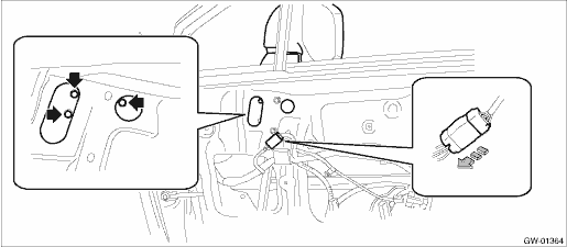
4. Remove the outer mirror assembly.
(1) Remove the connector clip that is installed on the panel assembly - front door, and disconnect the connector.
(2) Turn over the sealing cover - front door.
(3) Remove the bolts to remove outer mirror assembly.
 Assembly
GLASS/WINDOWS/MIRRORS > Outer Mirror AssemblyASSEMBLYCAUTION:• Be careful not to catch the harness in between the parts.• When installing the mirror - repair, insert the connector and c ...
 Disassembly
GLASS/WINDOWS/MIRRORS > Outer Mirror AssemblyDISASSEMBLYCAUTION:When removing the mirror - repair, be careful not to damage the back surface of mirror - repair with a flat tip screwdriver.1. Operat ...
Other materials:
USB memory
Audio files on the USB memory can be
played.
WARNING
Do not operate the player's controls
or connect the USB memory while
driving. Doing so may result in
losing control of your vehicle and
cause an accident or serious injury.
CAUTION
Do not leave your USB memory
in the car. In particul ...
Removal
INTAKE (INDUCTION)(H4DO) > Air Cleaner ElementREMOVAL1. Disconnect the ground cable from battery. NOTE">2. Remove the air intake duct. Air Intake Duct > REMOVAL">3. Disconnect the connector (A) from the mass air flow and intake air temperature sensor, and remove the clip (B). ...
Dtc c1222 front left abs sensor signal
VEHICLE DYNAMICS CONTROL (VDC) (DIAGNOSTICS) > Diagnostic Procedure with Diagnostic Trouble Code (DTC)DTC C1222 FRONT LEFT ABS SENSOR SIGNALNOTE:For the diagnostic procedure, refer to “DTC C1242 REAR LEFT ABS SENSOR SIGNAL”. Diagnostic Procedure with Diagnostic Trouble Code (DTC) > ...
