Subaru Crosstrek Service Manual: Installation
MECHANICAL(H4DO) > Chain Cover
INSTALLATION
1. Install the O-rings to cylinder head RH, cylinder head LH, cylinder block LH and oil pan upper.
NOTE:
• Use new O-rings.
• Apply a coat of engine oil to the O-rings.
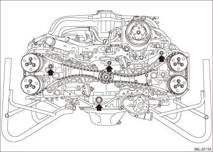
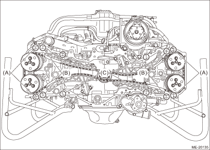
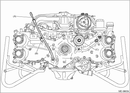
2. Apply liquid gasket if there are gaps between front camshaft cap and cam carrier (A), cam carrier and cylinder head (B), and cylinder head and cylinder block (C) as shown in the figure.
Liquid gasket:
THREE BOND 1217G (Part No. K0877Y0100), THREE BOND 1217H or equivalent
3. Apply liquid gasket to the chain cover mating surface and center boss (5 places) as shown in the figure.
NOTE:
• Before applying liquid gasket, degrease the old liquid gasket seal surface of the engine and chain cover.
• Install within 5 min. after applying liquid gasket.
Liquid gasket:
THREE BOND 1217G (Part No. K0877Y0100), THREE BOND 1217H or equivalent
Liquid gasket applying diameter:
4±0.5 mm (0.1575±0.0197 in)
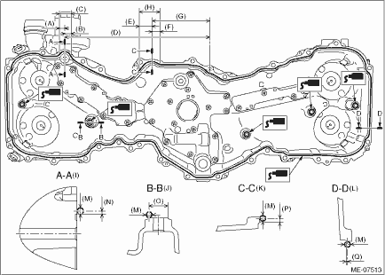
(A) | 14.5 mm (0.5709 in) | (G) | 127 mm (5.0000 in) | (M) | φ4±0.5 mm (0.1575±0.0197 in) |
(B) | 17.5 mm (0.6890 in) | (H) | Range B | (N) | 2 mm (0.0787 in) |
(C) | Range A | (I) | Liquid gasket applying position of mating surfaces of range A | (O) | φ12 mm (0.4724 in) |
(D) | 316.2 mm (12.4488 in) | (J) | Liquid gasket applying position of center boss (5 places) | (P) | 2.5 mm (0.0984 in) |
(E) | 24.5 mm (0.9646 in) | (K) | Liquid gasket applying position of mating surfaces of range B | (Q) | 0.5 mm (0.0197 in) |
(F) | 18.5 mm (0.7283 in) | (L) | Liquid gasket applying position of mating surfaces other than range A and range B |
4. Set the chain cover, and tighten the bolts in numerical order as shown in the figure.
CAUTION:
The chain cover may contact the protrusion (a) of cam sprocket sensor plate and cause damage. When setting the chain cover, move the chain cover horizontally and set it while taking care not to contact with the cam sprocket.
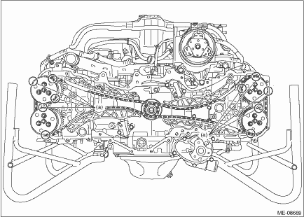
Tightening torque:
T1: 10 N·m (1.0 kgf-m, 7.4 ft-lb)
T2: 25 N·m (2.5 kgf-m, 18.4 ft-lb)
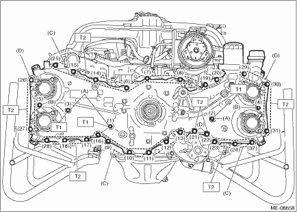
(A) | M6 ? 20 | (C) | M8 ? 25 | (D) | M8 ? 60 |
(B) | M6 ? 50 |
5. Install the idler pulley (C) and oil level gauge guide (B), and insert the oil level gauge (A).
NOTE:
• When installing the idler pulley, be careful of the idler pulley cover direction.
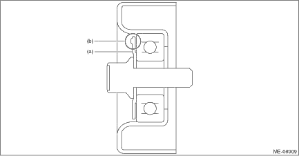
(a) | Idler pulley cover | (b) | Protrusion (3 places) |
• Use a new O-ring to the oil level gauge guide.
• Apply a light coat of engine oil to the O-rings of the oil level gauge guide and the oil level gauge.
Tightening torque:
T1: 6.4 N·m (0.7 kgf-m, 4.7 ft-lb)
T2: 36 N·m (3.7 kgf-m, 26.6 ft-lb)
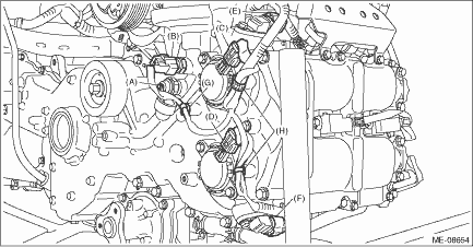
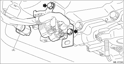
6. Connect the terminal (A) to the oil pressure switch, connector (B) to the engine oil temperature sensor, connector (C) to the intake oil control solenoid LH, connector (D) to the exhaust oil control solenoid LH, connector (E) to the intake camshaft position sensor LH, and connector (F) to the exhaust camshaft position sensor LH, and secure the engine harness with the clips (G) and (H).
NOTE:
The oil pressure switch harness must be positioned toward the left lower side of the vehicle within the range of 90°.
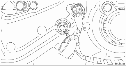
(a) | Left side of vehicle |
Tightening torque:
1.5 N·m (0.2 kgf-m, 1.1 ft-lb)
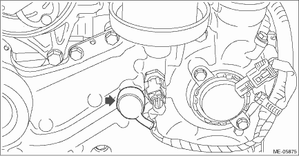
7. Attach the rubber cap to the oil pressure switch.
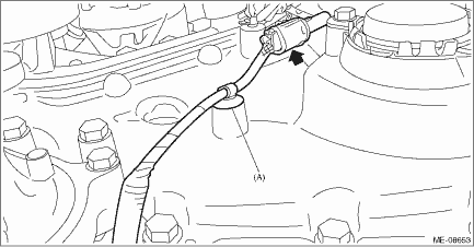
8. Secure the oil level switch harness with clips (A), and connect the connectors to the oil level switch.
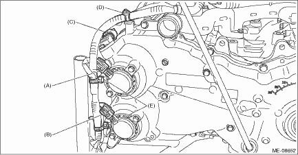
9. Connect the connector (A) to the intake oil control solenoid RH, connector (B) to the exhaust oil control solenoid RH, and connector (C) to the intake camshaft position sensor RH, and then secure the engine harness with the clips (D) and (E).
10. Connect the connector (A) to the exhaust camshaft position sensor RH, and install the engine harness stay to the chain cover.
Tightening torque:
6.4 N·m (0.7 kgf-m, 4.7 ft-lb)
11. Install the crank pulley. Crank Pulley > INSTALLATION">
12. Install the water pump pulley. Water Pump > INSTALLATION">
13. Install the generator. Generator > INSTALLATION">
14. Fill engine oil. Engine Oil > REPLACEMENT">
15. When working on the vehicle
NOTE:
When working on the vehicle, perform the following steps also.
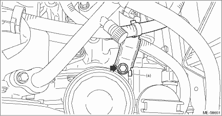
(1) Install the generator cord stay to the chain cover.
NOTE:
Install the generator cord stay so that the folded end (a) touches the chain cover boss.
Tightening torque:
8 N·m (0.8 kgf-m, 5.9 ft-lb)
(2) Install the front exhaust pipe. Front Exhaust Pipe > INSTALLATION">
(3) Install the radiator. Radiator > INSTALLATION">
 Inspection
MECHANICAL(H4DO) > Chain CoverINSPECTIONCheck that the chain cover does not have deformation, cracks and any other damage. ...
 Crank pulley
...
Other materials:
Dtc p0711 transmission fluid temperature sensor "a" circuit range/performance
CONTINUOUSLY VARIABLE TRANSMISSION (DIAGNOSTICS) > Diagnostic Procedure with Diagnostic Trouble Code (DTC)DTC P0711 TRANSMISSION FLUID TEMPERATURE SENSOR "A" CIRCUIT RANGE/PERFORMANCEDTC DETECTING CONDITION:Detected when two consecutive driving cycles with fault occur.TROUBLE SYMPTOM:&b ...
Removal
EXHAUST(H4DO) > MufflerREMOVALCAUTION:Vehicle components are extremely hot after driving. Be wary of receiving burns from heated parts.1. Turn the ignition switch to OFF.2. Lift up the vehicle.3. Remove the bolts and self-locking nuts which secure the rear exhaust pipe to the muffler.4. Apply a c ...
Removal
CONTINUOUSLY VARIABLE TRANSMISSION(TR580) > Air Breather HoseREMOVAL1. FRONT DIFFERENTIAL SIDE1. Remove the clip (A) from the air intake boot.2. Loosen the clamp (B) connecting the air intake boot and air cleaner case (rear).3. Loosen the clamp (C) which connects the air intake boot and throttle ...
