Subaru Crosstrek Service Manual: Disassembly
CONTROL SYSTEMS > Select Lever
DISASSEMBLY
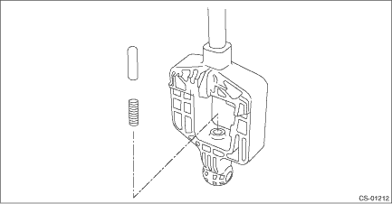
1. GRIP ASSY
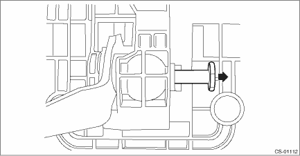
1. Remove the button assembly_AT.
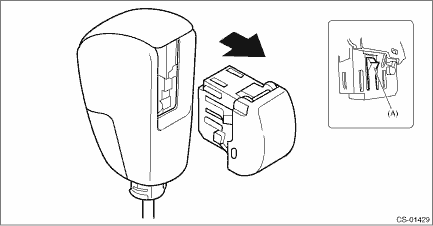
(A) | Claw |
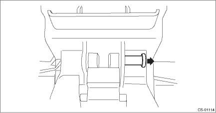
2. Remove the rod COMPL.
2. AT SELECT LEVER ASSEMBLY
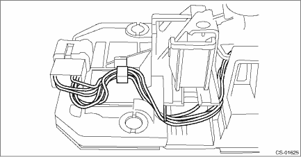
1. Remove the spacer plate.
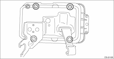
2. Remove the gasket.
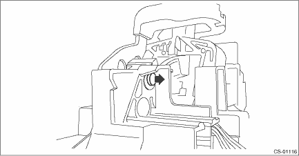
3. Insert a flat tip screwdriver with a thin tip under the connector and disconnect the harness connector from the plate COMPL.
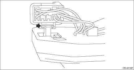
4. Remove the harness from the plate COMPL.
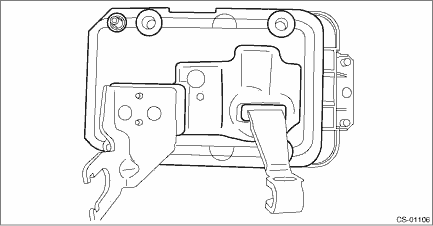
5. Raise the claw with a flat tip screwdriver with a thin tip and remove the solenoid unit.
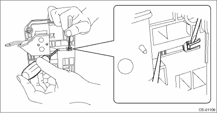
6. Remove the terminal of the solenoid unit using a flat tip precision screwdriver with a tip width of 1.3 mm (0.05 in) or less, KTC connector terminal tool ECC-1T or equivalent.
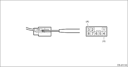
(A) | Solenoid unit terminals |
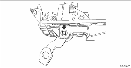
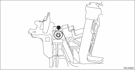
7. Remove the clamp push nut.
NOTE:
Replace the clamp push nut with a new part.
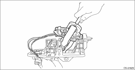
8. Pull out shaft control.
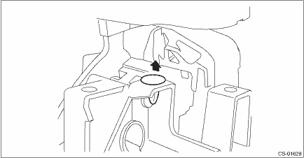
9. Remove the clamp push nut.
NOTE:
Replace the clamp push nut with a new part.
10. Pull out spacer pin guide.
11. Remove the clamp pin.
12. Remove the spacer pin guide.
13. Remove the select lever COMPL from the plate COMPL.
14. Remove the arm COMPL.
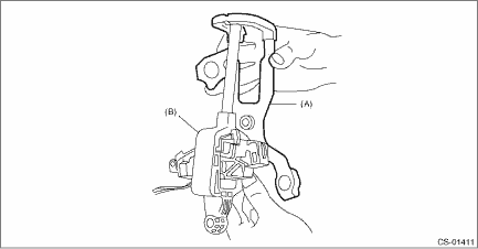
(A) | Arm COMPL |
(B) | Select lever COMPL |
15. Remove the plate guide from the select lever COMPL.
16. Remove the rod detent and detent spring from the select lever COMPL.
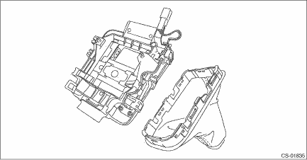
3. INDICATOR ASSY
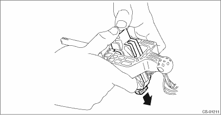
1. Remove the boot assembly from the indicator assembly.
CAUTION:
When removing the boot assembly, be careful not to damage the boot assembly claws and adjacent parts.
 Removal
CONTROL SYSTEMS > Select LeverREMOVAL1. Shift the select lever to “N” range.2. Disconnect the ground cable from battery. NOTE">NOTE:For model with battery sensor, disconnect th ...
 Inspection
CONTROL SYSTEMS > Select LeverINSPECTION1. Inspect the removed parts by comparing with new parts for deformation, damage and wear. Repair or replace if defective.2. Inspect the select lever assembl ...
Other materials:
Electrical specification
AUTO HEADLIGHT BEAM LEVELER SYSTEM (DIAGNOSTICS) > Control Module I/O SignalELECTRICAL SPECIFICATION1. AUTO HEADLIGHT BEAM LEVELER CMContentTerminal No.Measuring conditionStandardIG power supply1 ←> Chassis groundIgnition switch ON8 — 16 VGND2 ←> Chassis groundAlwaysLess than 1 ...
Check list for interview Check
BODY CONTROL SYSTEM (DIAGNOSTICS) > Check List for InterviewCHECKInspect the following items regarding the vehicle’s state.Body Control System Check List for Interview Date of Vehicle Bring-in Year Month Day Customer’s ...
Switches and harness
Inspection
Blind Spot Detection/Rear Cross Traffic Alert > Switches and HarnessINSPECTIONBSD/RCTA OFF switch1. Measure the resistance between connector terminals.Preparation tool:Circuit testerTerminal No.Inspection conditionsStandard1 — 2Switch OFF1 M? or moreSwitch ONLess than 1 ?2. Apply ba ...
