Subaru Crosstrek Service Manual: Removal
CONTROL SYSTEMS > Select Lever
REMOVAL
1. Shift the select lever to “N” range.
2. Disconnect the ground cable from battery. NOTE">
NOTE:
For model with battery sensor, disconnect the ground terminal from battery sensor.
3. Lift up the vehicle.
4. Remove the center exhaust pipe. Center Exhaust Pipe > REMOVAL">
5. Remove the center exhaust cover.
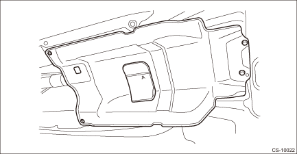
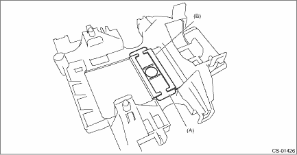
6. Disconnect the cable from the arm COMPL.
CAUTION:
Do not apply extra overload while holding the part (A).
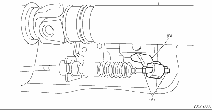
(A) | Adjusting nut |
(B) | Arm COMPL |
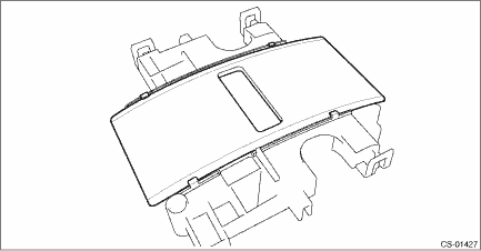
7. Raise the claw of clamp and remove the cable.
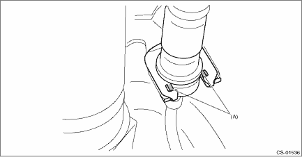
(A) | Claw |
8. Lower the vehicle.
9. Shift the select lever to “N” range.
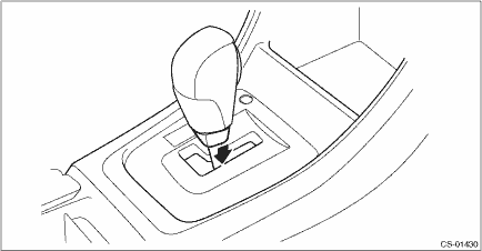
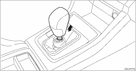
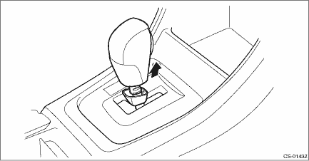
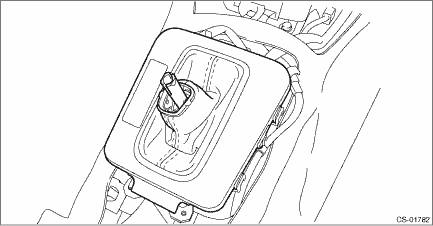
10. Lower the boot assembly vertically toward the lever. (Model with boot shifter)
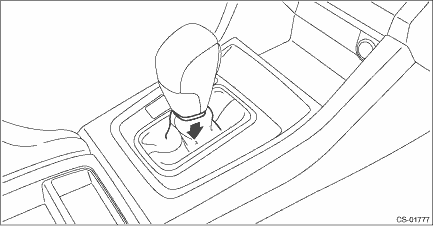
11. Lower the cover grip AT vertically toward the lever. (Model with gate shifter)
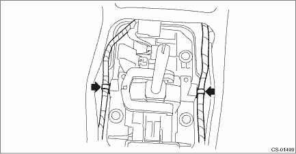
12. Remove the clamp grip pin.
• Model with boot shifter
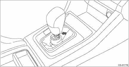
• Model with gate shifter
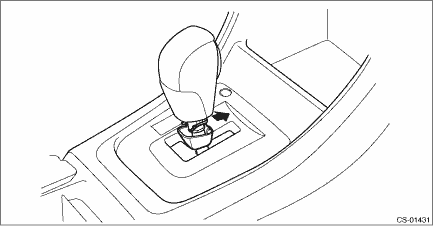
13. Remove the grip assembly.
• Model with boot shifter
• Model with gate shifter
14. Remove the console box. Console Box > REMOVAL">
15. Remove the cover - shift lever. Console Box > REMOVAL">
16. Disconnect the connector, and remove the indicator cover from the housing. (Model with gate shifter)
17. Remove the housing with the blind A and blind B. (Model with gate shifter)
18. Remove the blind B. (Model with gate shifter)
(A) | Blind B |
(B) | Blind A |
19. Remove the blind A from the housing. (Model with gate shifter)
20. Remove the panel center LWR LH and RH. Console Box > REMOVAL">
21. Disconnect the connector, and remove the indicator assembly. (Model with boot shifter)
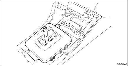
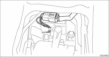
22. Remove the harness clip from the select lever assembly.
23. Disconnect the harness connector.
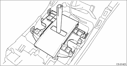
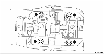
24. Remove the four bolts to remove the select lever assembly.
 Assembly
CONTROL SYSTEMS > Select LeverASSEMBLY1. Clean all the parts before assembly.2. Apply Multemp D or equivalent to the sliding portion of each part.3. Assemble in the reverse order of disassembly.NOT ...
 Disassembly
CONTROL SYSTEMS > Select LeverDISASSEMBLY1. GRIP ASSY1. Remove the button assembly_AT.(A)Claw2. Remove the rod COMPL.2. AT SELECT LEVER ASSEMBLY1. Remove the spacer plate.2. Remove the gasket.3. In ...
Other materials:
Removal
LIGHTING SYSTEM > Tail/Stop Light BulbREMOVAL1. CROSSTREK MODEL1. Disconnect the ground cable from battery. NOTE">2. Remove the light assembly - rear combination.CAUTION:Be careful not to damage the clips.(1) Release the bolts and clips, then pull out the light assembly - rear combinatio ...
Installation
BRAKE > Front Disc RotorINSTALLATIONNOTE:Before installation, remove mud and foreign matter from the caliper body assembly.1. Before installation, check the front disc rotor. Front Disc Rotor > INSPECTION">2. Install each part in the reverse order of removal.Tightening torque:Brake ho ...
Assembly
CONTINUOUSLY VARIABLE TRANSMISSION(TR580) > Extension CaseASSEMBLY1. Press-fit the dust cover into extension case.2. Install the extension case oil seal to extension case. Differential Side Retainer Oil Seal > REPLACEMENT">3. Install all plugs.NOTE:• Use a new O-ring or a gasket ...
