Subaru Crosstrek Service Manual: Assembly
CONTROL SYSTEMS > Select Lever
ASSEMBLY
1. Clean all the parts before assembly.
2. Apply Multemp D or equivalent to the sliding portion of each part.
3. Assemble in the reverse order of disassembly.
NOTE:
Insert the solenoid unit terminals to the harness connector.
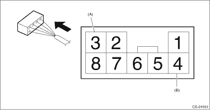
(A) | Solenoid unit (color code: blue) |
(B) | Solenoid unit (color code: black) |
4. After installation, check the following points.
• The select indicator matches the select lever position when the select lever is changed from “P” range to “D” range.
• The select lever position and the position mark match each other.
• Operating force to move the select lever from “P” to “D” range
 Select lever
...
 Removal
CONTROL SYSTEMS > Select LeverREMOVAL1. Shift the select lever to “N” range.2. Disconnect the ground cable from battery. NOTE">NOTE:For model with battery sensor, disconnect th ...
Other materials:
Dtc u0402 invalid data received from tcm
HVAC SYSTEM (AUTO A/C) (DIAGNOSTICS) > Diagnostic Procedure with Diagnostic Trouble Code (DTC)DTC U0402 INVALID DATA RECEIVED FROM TCMThis is detected when CAN data from TCM is abnormal.NOTE:Perform the diagnosis for LAN system. Basic Diagnostic Procedure > PROCEDURE"> ...
Dtc p0017 crankshaft position - camshaft position correlation bank 1 sensor b
ENGINE (DIAGNOSTICS)(H4DO) > Diagnostic Procedure with Diagnostic Trouble Code (DTC)DTC P0017 CRANKSHAFT POSITION - CAMSHAFT POSITION CORRELATION BANK 1 SENSOR BDTC detecting condition:Detected when two consecutive driving cycles with fault occur.Trouble symptom:• Engine stall• Improp ...
Caution
HVAC SYSTEM (HEATER, VENTILATOR AND A/C) > General DescriptionCAUTION• Before disassembling or reassembling parts, always disconnect the battery ground cable from battery. When replacing the radio, control module, and other parts provided with memory functions, record the memory contents be ...
