Subaru Crosstrek Service Manual: Installation
CONTINUOUSLY VARIABLE TRANSMISSION(TR580) > Drive Pinion Shaft Assembly
INSTALLATION
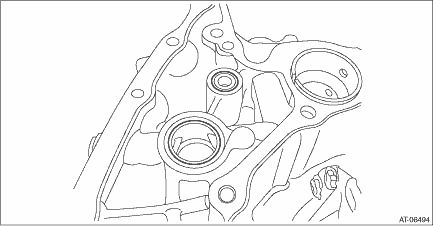
1. Clean the mating surface of drive pinion retainer and converter case.
2. Adjust the backlash and tooth contact between drive pinion shaft assembly and the front differential side gear. Drive Pinion Shaft Assembly > ADJUSTMENT">
3. Install O-rings in two locations to the converter case.
NOTE:
• Use new O-rings.
• Apply CVTF to the O-ring.

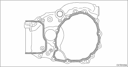
4. Apply liquid gasket seamlessly to the mating surface of drive pinion retainer.
Liquid gasket:
THREE BOND 1215B or equivalent

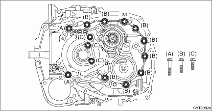
5. Install the drive pinion retainer to converter case, and tighten the bolt using the ST.
| ST 18270KA020 | SOCKET (E20) |
NOTE:
Do not confuse the three different-length bolts when installing.
Tightening torque:
43 N·m (4.4 kgf-m, 31.7 ft-lb)

6. Install the forward clutch assembly. Forward Clutch Assembly > INSTALLATION">
7. Install the reverse brake assembly. Reverse Brake Assembly > INSTALLATION">
8. Install the primary pulley, secondary pulley and variator chain. Primary Pulley and Secondary Pulley > INSTALLATION">
9. Install the reduction drive gear. Reduction Drive Gear > INSTALLATION">
10. Install the transmission case. Transmission Case > INSTALLATION">
11. Install the transmission control device. Transmission Control Device > INSTALLATION">
12. Install the oil strainer and oil pan. Oil Pan and Strainer > INSTALLATION">
13. Install the reduction driven gear assembly. Reduction Driven Gear > INSTALLATION">
14. Install the transfer driven gear assembly. Transfer Driven Gear > INSTALLATION">
15. Install the transfer clutch assembly. Transfer Clutch > INSTALLATION">
16. Install the parking pawl. Parking Pawl > INSTALLATION">
17. Install the extension case. Extension Case > INSTALLATION">
18. Install the inhibitor switch. Inhibitor Switch > INSTALLATION">
19. Install the secondary speed sensor. Secondary Speed Sensor > INSTALLATION">
20. Install the primary speed sensor. Primary Speed Sensor > INSTALLATION">
21. Install the turbine speed sensor. Turbine Speed Sensor > INSTALLATION">
22. Install the transmission harness. Transmission Harness > INSTALLATION">
23. Install the control valve body. Control Valve Body > INSTALLATION">
24. Install the air breather hose. Air Breather Hose > INSTALLATION">
25. Install the transmission assembly to the vehicle. Automatic Transmission Assembly > INSTALLATION">
 Inspection
CONTINUOUSLY VARIABLE TRANSMISSION(TR580) > Drive Pinion Shaft AssemblyINSPECTION• Make sure that all component parts are free of scratches, holes and other faults.• Check the tooth con ...
 Drive plate
...
Other materials:
Control screen and audio panel
Select to display the audio source
selection screen.
Select to display the play mode
currently selected. Refer to "Select
play mode"
Select to display folder list.
Shows progress.
The tracks in the folder are played
back 10 seconds each from the
beginning of the track.
Sel ...
Inspection
CONTINUOUSLY VARIABLE TRANSMISSION(TR580) > Reverse Brake AssemblyINSPECTION• Inspect the drive plate facing for wear and damage.• Check the driven plate for discoloration (burnt color).• Check for worn snap ring, fatigue or damaged return spring or deformed spring retainer.&bul ...
Power door locking switches
Lock
Unlock
All doors and the rear gate can be locked
and unlocked by the power door locking
switches located at the driver's side and
the front passenger's side doors.
To lock the doors, push the front side of
the switch.
To unlock the doors, push the rear side of
the switch. ...
