Subaru Crosstrek Owners Manual: Fuses
CAUTION
Never replace a fuse with one having a higher rating or with material other than a fuse because serious damage or a fire could result.
The fuses are designed to melt during an overload to prevent damage to the wiring harness and electrical equipment. The fuses are located in two fuse boxes.
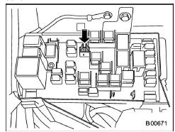
One is located under the instrument panel behind the fuse box cover on the driver's seat side. To remove the cover, pull it out.
1) Spare fuses
The other one (main fuse box) is housed in the engine compartment. Also, the spare fuses are stored in the fuse box cover.
The fuse puller is stored in the main fuse box in the engine compartment.
- Good
- Blown
If any lights, accessories or other electrical controls do not operate, inspect the corresponding fuse. If a fuse has blown, replace it.
1. Turn the ignition switch to the "LOCK"/ "OFF" position and turn off all electrical accessories.
2. Remove the cover.
3. Determine which fuse may be blown.
Look at the back side of each fuse box cover and refer to "Fuses and circuits" F12-9.
4. Pull out the fuse with the fuse puller.
5. Inspect the fuse. If it has blown, replace it with a spare fuse of the same rating.
6. If the same fuse blows again, this indicates that its system has a problem.
Contact your SUBARU dealer for repairs.
 Battery
WARNING
Before beginning work on or near
any battery, be sure to extinguish
all cigarettes, matches, and lighters.
Never expose a battery to an
open flame or electric sparks.
Batteri ...
 Installation of accessories
Always consult your SUBARU dealer
before installing fog lights or any other
electrical equipment in your vehicle. Such
accessories may cause the electronic
system to malfunction if they are incorr ...
Other materials:
Dtc b2329 rear radar axis alignment incomplete
Blind Spot Detection/Rear Cross Traffic Alert (DIAGNOSTICS) > Diagnostic Procedure with Diagnostic Trouble Code (DTC)DTC B2329 REAR RADAR AXIS ALIGNMENT INCOMPLETEDTC DETECTING CONDITION:Axis adjustment of the radar sensor has failed.(Forced termination of the Subaru Select Monitor, improper loca ...
Dtc b1832 short in curtain airbag rh squib circuit (to ground)
AIRBAG SYSTEM (DIAGNOSTICS) > Diagnostic Chart with Trouble CodeDTC B1832 SHORT IN CURTAIN AIRBAG RH SQUIB CIRCUIT (TO GROUND)Diagnosis start condition:Ignition voltage is 10 V to 16 V.DTC detecting condition:• Curtain airbag harness (RH) circuit is shorted to ground.• Curtain airbag ...
Dtc b2311 rear radar detect tcm
Blind Spot Detection/Rear Cross Traffic Alert (DIAGNOSTICS) > Diagnostic Procedure with Diagnostic Trouble Code (DTC)DTC B2311 REAR RADAR DETECT TCMDTC DETECTING CONDITION:Automatic transmission fails.TROUBLE SYMPTOM:• All functions of BSD/RCTA stop.• Fail icon is displayed in the com ...
