Subaru Crosstrek Service Manual: Connector symbol in wiring harness
WIRING SYSTEM > Basic Diagnostic Procedure
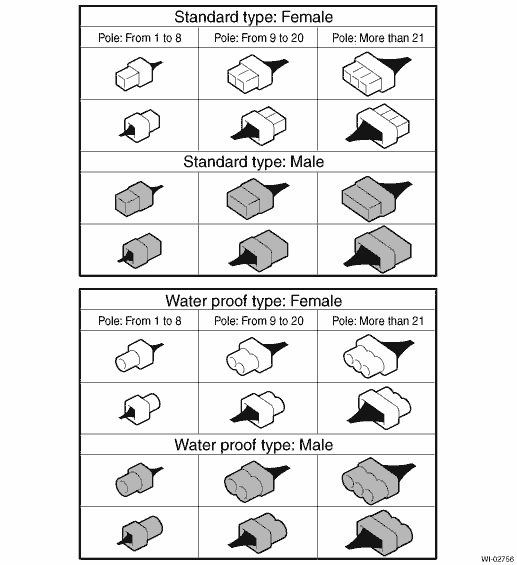
CONNECTOR SYMBOL IN WIRING HARNESS
A number of connector symbols are used in each wiring diagram to easily identify the wiring harness connectors.
 Basic procedures
WIRING SYSTEM > Basic Diagnostic ProcedureBASIC PROCEDURES1. GENERAL DESCRIPTIONThe most important purpose of diagnostics is to quickly determine which part is malfunctioning, to save time and labo ...
 Basic inspection
WIRING SYSTEM > Basic Diagnostic ProcedureBASIC INSPECTION1. VOLTAGE MEASUREMENT1. Using a voltmeter, connect the negative lead to a good ground point or negative battery terminal and the positive ...
Other materials:
Interruption screen
Warning information (display example)
Useful messages, such as reminder information,
vehicle information, warning
information, etc. may interrupt the current
screen and appear on the display accompanied
by a beep. Take proper action
according to the message.
The warning screen will retu ...
Installation
BRAKE > Front Brake PadINSTALLATIONNOTE:Before installation, remove mud and foreign matter from the caliper body assembly and support - front disc brake.1. Check the brake pad. Front Brake Pad > INSPECTION">2. Apply a thin coat of grease to the pad clip.Preparation items:Grease: An it ...
Operation
Driver's side
Passenger's side
SRS AIRBAGs deploy as soon as a collision occurs.
After deployment, SRS AIRBAGs start to deflate immediately so that the
driver's vision is not
obstructed.
The SRS airbags can function only when
the ignition switch is in the "ON" position.
Th ...
