Subaru Crosstrek Service Manual: Installation
BRAKE > Front Brake Pad
INSTALLATION
NOTE:
Before installation, remove mud and foreign matter from the caliper body assembly and support - front disc brake.
1. Check the brake pad. Front Brake Pad > INSPECTION">
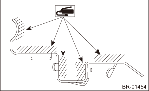
2. Apply a thin coat of grease to the pad clip.
Preparation items:
Grease: An item contained in the pad kit or equivalent
3. Install the brake pad to the support - front disc brake.
CAUTION:
• Be sure to install so that the pad return spring faces the input side of the direction of brake rotor rotation, as shown in the figure.
• Correctly install the pad return spring to the supporting surface of the pad clip as shown in the figure.
• If the pad return spring is deformed or damaged, replace the brake pad with a new part.
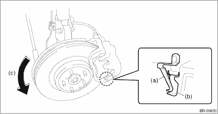
(a) | Pad return spring | (b) | Supporting surface of pad clip | (c) | Direction of brake rotor rotation |
NOTE:
Install the brake pad indicator in proper direction.
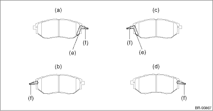
(a) | LH — IN | (c) | RH — IN | (e) | Pad indicator |
(b) | LH — OUT | (d) | RH — OUT | (f) | Pad return spring |
4. Install the caliper body assembly to the support - front disc brake.
Tightening torque:
Caliper bolt: 27 N·m (2.75 kgf-m, 19.9 ft-lb)
5. Install the front wheels.
Tightening torque:
Except for C4 model: 120 N·m (12.24 kgf-m, 88.5 ft-lb)
C4 model: 100 N·m (10.20 kgf-m, 73.8 ft-lb)
 Removal
BRAKE > Front Brake PadREMOVAL1. Lift up the vehicle, and then remove the front wheels.2. Remove the front brake pad.(1) Remove the caliper bolt on the lower side.(2) Raise the caliper body assembl ...

Other materials:
Dtc u1120 lost communication with autostart stop control module
LAN SYSTEM (DIAGNOSTICS) > Diagnostic Procedure with Diagnostic Trouble Code (DTC)DTC U1120 LOST COMMUNICATION WITH AUTOSTART STOP CONTROL MODULENOTE:The electric power steering CM identifies whether the Auto Start Stop function is provided or not using information from the combination meter. The ...
Preparation tool
SECURITY AND LOCKS > General DescriptionPREPARATION TOOL1. SPECIAL TOOLILLUSTRATIONTOOL NUMBERDESCRIPTIONREMARKS — SUBARU SELECT MONITOR 4Used for setting of each function and troubleshooting for electrical system.NOTE:For detailed operation procedures of Subaru Select Monitor 4, refer to &ldqu ...
Dtc b2a06 right speaker/audio circuit
TELEMATICS SYSTEM (DIAGNOSTICS) > Diagnostic Procedure with Diagnostic Trouble Code (DTC)DTC B2A06 RIGHT SPEAKER/AUDIO CIRCUITDiagnosis start condition:When ACC is ON.DTC detecting condition:Speaker impedance is more than 10 k? for 100 ms. (Detached speaker connection, etc.)Trouble symptom:• ...
