Subaru Crosstrek Service Manual: Component
DRIVE SHAFT SYSTEM > General Description
COMPONENT
1. PROPELLER SHAFT
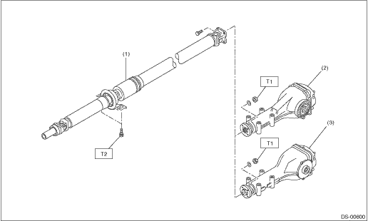
(1) | Propeller shaft | (3) | Rear differential (T-type) | Tightening torque: N·m (kgf-m, ft-lb) | |
(2) | Rear differential (VA1-type) | T1: | 31 (3.2, 22.9) | ||
T2: | 52 (5.3, 38.4) | ||||
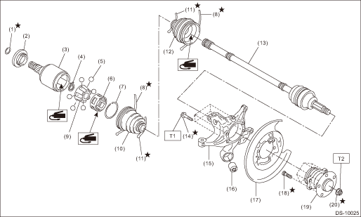
2. FRONT AXLE
• EBJ + PTJ type

(1) | Circlip | (8) | Boot (PTJ) | (15) | Front hub unit bearing |
(2) | Baffle plate | (9) | O-ring | (16) | Axle nut |
(3) | Outer race (PTJ) | (10) | Shaft ASSY (EBJ) | ||
(4) | Snap ring | (11) | Bolt | Tightening torque: N·m (kgf-m, ft-lb) | |
(5) | Trunnion | (12) | Front axle housing | T1: | 220 (22.4, 162.3) |
(6) | Snap ring | (13) | Front brake back plate | T2: | 65 (6.6, 47.9) |
(7) | Boot band | (14) | Hub bolt | ||
3. REAR AXLE
(1) | Circlip | (9) | Inner race | (17) | Rear brake back plate |
(2) | Baffle plate | (10) | Boot (DOJ) | (18) | Hub bolt |
(3) | Outer race (DOJ) | (11) | Boot band | (19) | Rear hub unit bearing |
(4) | Snap ring | (12) | Boot (BJ) Boot (EBJ) | (20) | Axle nut |
(5) | Ball | (13) | Shaft ASSY (BJ) (CVT model) Shaft ASSY (EBJ) (MT model) | ||
(6) | Cage | (14) | Bolt | Tightening torque: N·m (kgf-m, ft-lb) | |
(7) | Snap ring | (15) | Rear axle housing | T1: | 65 (6.6, 47.9) |
(8) | Boot band | (16) | Rear bushing | T2: | 190 (19.4, 140.1) |
 Specification
DRIVE SHAFT SYSTEM > General DescriptionSPECIFICATION1. PROPELLER SHAFTPropeller shaft typeEDJFront propeller shaft joint-to-joint length: L1CVT675.5 mm (26.59 in)MT735.5 mm (28.96 in)Rear propelle ...
 Preparation tool
DRIVE SHAFT SYSTEM > General DescriptionPREPARATION TOOL1. SPECIAL TOOLILLUSTRATIONPART NO.DESCRIPTIONREMARKS20099PA010INSTALLER & REMOVER• Used for replacing the rear bushing of rear axl ...
Other materials:
Removal
SECURITY AND LOCKS > Access BuzzerREMOVAL1. Disconnect the ground cable from battery. NOTE">2. Lift up the vehicle.3. Remove the clips and screws, and turn over the front side of the mud guard - front RH.4. Remove the access buzzer.(1) Disconnect the connector.(2) Remove the clip and det ...
Dtc b1577 imm control module eeprom
KEYLESS ACCESS WITH PUSH BUTTON START SYSTEM (DIAGNOSTICS) > Diagnostic Procedure with Diagnostic Trouble Code (DTC)DTC B1577 IMM CONTROL MODULE EEPROM1. EXCEPT FOR C0 AND C5 MODELSDTC detecting condition:• Defective keyless access CM• When inaccessible to ROM in keyless access CM.STE ...
U.S.-spec. models (type B)
The illustration above is a typical example. For some models, the combination
meter
may be slightly different than that shown in the illustration.
Tachometer
Multi information display
Fuel gauge
Select lever/gear position indicator
Speedometer
Information display selection knob
...
