Subaru Crosstrek Service Manual: Assembly
MANUAL TRANSMISSION AND DIFFERENTIAL(5MT) > Drive Pinion Shaft Assembly
ASSEMBLY
1. Install the sleeve and the gear and hub assembly by matching the alignment marks.
NOTE:
• Make sure that there is no large clearance at both sides of the 1st-2nd shifting insert after assembly.
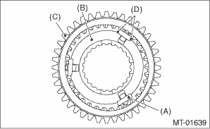
(A) | 1st-2nd shifting insert |
(B) | 1st-2nd synchronizer hub |
(C) | Reverse driven gear |
(D) | There is no large clearance at this part. |
• Use the new gear & hub assembly, if replacing the gear or hub.
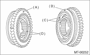
(A) | 1st gear side |
(B) | 2nd gear side |
(C) | Flush surface |
(D) | Stepped surface |
2. Install the 1st driven gear, inner baulk ring, synchro cone, outer baulk ring, and gear & hub assembly.
NOTE:
• Install the gear & hub assembly in the proper position while paying attention to the installing direction.
• Align the baulk ring and gear & hub assembly with the key groove.
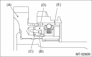
(A) | 1st driven gear |
(B) | Synchro cone |
(C) | Inner baulk ring |
(D) | Outer baulk ring |
(E) | Gear & hub |
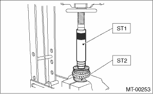
3. Install the 2nd driven gear bushing using ST1, ST2 and a press.
CAUTION:
Do not apply a load in excess of 10 kN (1 ton, 1.1 US ton, 1.0 Imp ton).
NOTE:
• Attach a cloth to the end of the driven shaft to prevent damage.
• When press fitting, align the oil holes of the shaft and bushing.
| ST1 499277200 | INSTALLER |
| ST2 499587000 | INSTALLER |
4. Attach and insert the 2nd driven gear, inner baulk ring, synchro cone and outer baulk ring.
NOTE:
Align the groove of the baulk ring with the 1st-2nd shifting insert.
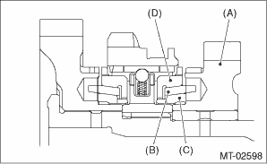
(A) | 2nd driven gear |
(B) | Synchro cone |
(C) | Inner baulk ring |
(D) | Outer baulk ring |
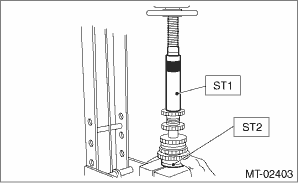
5. After installing key onto the driven shaft, install the 3rd-4th driven gear using ST1, ST2 and a press.
CAUTION:
Do not apply a load in excess of 10 kN (1 ton, 1.1 US ton, 1.0 Imp ton).
| ST1 499277200 | INSTALLER |
| ST2 499587000 | INSTALLER |
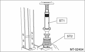
6. Install the set of double taper roller bearing using ST1, ST2 and a press.
CAUTION:
Do not apply a load in excess of 10 kN (1 ton, 1.1 US ton, 1.0 Imp ton).
NOTE:
Use a new double taper roller bearing.
| ST1 499277200 | INSTALLER |
| ST2 499587000 | INSTALLER |
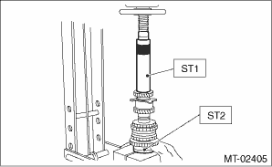
7. Position the woodruff key in groove of the rear of driven shaft. Install the 5th driven gear using ST1, ST2 and a press.
CAUTION:
Do not apply a load in excess of 10 kN (1 ton, 1.1 US ton, 1.0 Imp ton).
NOTE:
Face the groove for identification of the 5th driven gear toward the nut.
| ST1 499277200 | INSTALLER |
| ST2 499587000 | INSTALLER |
8. Install the lock washer. Tighten the lock nuts to the specified torque using ST1 and ST2.
NOTE:
• Use new lock nuts and lock washers.
• Make sure the lock washer is installed in the proper direction.
Tightening torque:
260 N·m (26.5 kgf-m, 191.8 ft-lb)
| ST1 499987300 | SOCKET WRENCH (50) |
| ST2 899884100 | HOLDER |
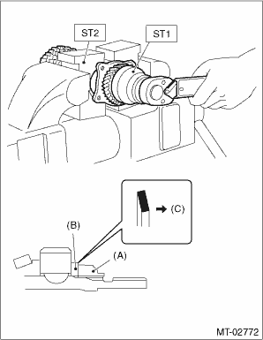
(A) | Lock nut |
(B) | Lock washer |
(C) | Nut side |
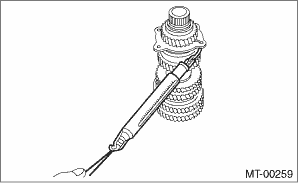
9. Using a spring scale, check that starting torque of the double taper roller bearing is 0.1 to 1.5 N (0.01 to 0.15 kgf, 0.02 to 0.34 lbf).
10. Crimp the lock nut at two locations so that the dimension (B) becomes 41.1 mm (1.62 in) or less.
CAUTION:
When crimping the lock nut, be careful not to crack it.
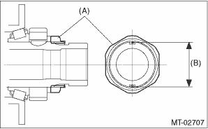
(A) | Lock nut |
(B) | Outer dimension after crimping |
11. Install the roller bearing.
NOTE:
• Use a new roller bearing.
• Install with the knock pin hole of the roller bearing outer race facing the rear side.
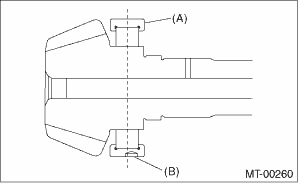
(A) | Roller bearing |
(B) | Knock pin hole |
12. Install the washer using ST1, ST2 and a press.
CAUTION:
Do not apply a load in excess of 10 kN (1 ton, 1.1 US ton, 1.0 Imp ton).
| ST1 499277100 | BUSHING 1-2 INSTALLER |
| ST2 499277200 | INSTALLER |
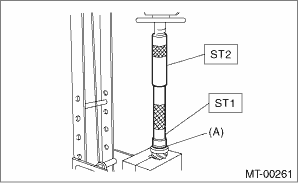
(A) | Washer |
13. Install the thrust bearing and needle bearing and install the driven shaft assembly.
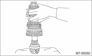
14. Install the drive pinion collar, needle bearing, adjusting washer No. 2, thrust bearing, adjusting washer No. 1 and differential bevel gear sleeve in this order.
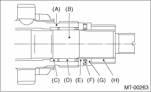
(A) | Driven shaft |
(B) | Drive pinion shaft |
(C) | Drive pinion collar |
(D) | Needle bearing (25 ? 30 ? 20) |
(E) | Adjusting washer No. 2 (25 ? 36 ? t) |
(F) | Thrust bearing (25 ? 37.5 ? 3) |
(G) | Adjusting washer No. 1 (25 ? 36 ? t) |
(H) | Differential bevel gear sleeve |
15. Adjust the thrust bearing preload. Drive Pinion Shaft Assembly > ADJUSTMENT">
 Removal
MANUAL TRANSMISSION AND DIFFERENTIAL(5MT) > Drive Pinion Shaft AssemblyREMOVAL1. Remove the manual transmission assembly from the vehicle. Manual Transmission Assembly > REMOVAL">2. Rem ...
 Disassembly
MANUAL TRANSMISSION AND DIFFERENTIAL(5MT) > Drive Pinion Shaft AssemblyDISASSEMBLYNOTE:Attach a cloth to the end of driven shaft (on the frictional side of the thrust needle bearing) to prevent dam ...
Other materials:
Inspection
HVAC SYSTEM (HEATER, VENTILATOR AND A/C) > Evaporator SensorINSPECTION1. MANUAL A/C MODELWIRING DIAGRAM:1. Prepare the vehicle.NOTE:Check that the ambient temperature is 25 — 40°C (77 — 104°F) and that the humidity is 30% — 80%.• Place the vehicle in the workshop ...
Replacement
MANUAL TRANSMISSION AND DIFFERENTIAL(5MT) > Differential Side Retainer Oil SealREPLACEMENT1. Disconnect the ground cable from battery.2. Remove the front tires.3. Lift up the vehicle.4. Using the TORX® bit T70, remove the drain plug, and drain the transmission gear oil completely.CAUTION:• ...
Operation
CONTINUOUSLY VARIABLE TRANSMISSION (DIAGNOSTICS) > AT OIL TEMP Warning Light DisplayOPERATIONThe AT OIL TEMP light illuminates or blinks, when the ATF temperature is high and malfunction occurs in CVT.• At normal conditionAfter turning the ignition switch to ON, illuminates for 2 seconds th ...
