Subaru Crosstrek Service Manual: Assembly
CONTINUOUSLY VARIABLE TRANSMISSION(TR580) > Drive Pinion Shaft Assembly
ASSEMBLY
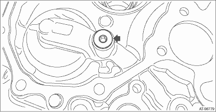
1. Install the plug to drive pinion retainer.
NOTE:
• Use new O-rings.
• Apply CVTF to the O-rings.
Tightening torque:
22 N·m (2.2 kgf-m, 16.2 ft-lb)
2. Using the ST, install the oil seal to drive pinion retainer.
NOTE:
• Apply CVTF to the oil seal press-fitting surface and lip.
• Install the oil seal in the correct direction.
| ST 927720000 | HOUSING BUSHING INSTALLER AND REMOVER |
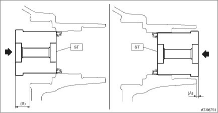
(A) | 2.8 mm (0.11 in) |
(B) | 18.7 mm (0.74 in) |
3. Select the drive pinion washer.
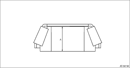
(1) Measure the roller bearing inner race width “A” on the front side.
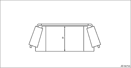
(2) Measure the roller bearing inner race width “B” on the rear side.
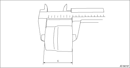
(3) Measure the spacer width “C”.
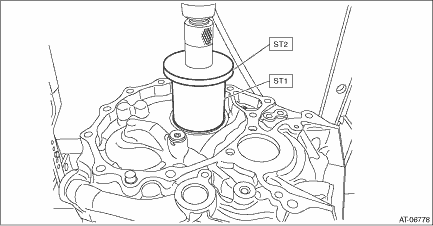
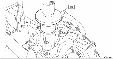
(4) Using the ST, install the front roller bearing outer race to the drive pinion retainer.
| ST1 28499TC010 | INSTALLER |
| ST2 398177700 | INSTALLER |
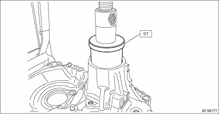
(5) Using the ST, install the rear roller bearing outer race to the drive pinion retainer.
| ST 20099AE020 | INSTALLER |
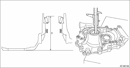
(6) Place the drive pinion retainer on the surface plate, and install the inner race to the rear roller bearing outer race.
NOTE:
Place the drive pinion retainer so that the mating surface of the drive pinion retainer (mating surface with the converter case) contacts the surface plate.
(7) Measure the height “D” from the end face of the rear roller bearing inner race to the surface plate.
(8) Install the inner race to the front roller bearing outer race.
(9) Measure the depth “E” from the end face of the front roller bearing inner race to the end face of the ST.
| ST 499575400 | GAUGE |

(10) Using following formula, select one to three drive pinion washers.
T (mm) = D − (A + B + C + E − 15) − (0±0.0125)
[T (in) = D − (A + B + C + E − 0.591) − (0±0.0005)]
A: Front roller bearing width
B: Rear roller bearing width
C: Spacer width
D: Height from end face of rear roller bearing inner race to surface plate
E: Depth from end face of front roller bearing inner race to end face of ST
15 mm (0.591 in): Thickness of ST
T: Drive pinion washer thickness
0±0.0125 mm (0±0.0005 in): Clearance
Drive pinion washer | |
Part No. | Thickness mm (in) |
38336AA750 | 0.150 (0.0059) |
38336AA760 | 0.175 (0.0069) |
38336AA770 | 0.200 (0.0079) |
38336AA780 | 0.225 (0.0089) |
38336AA790 | 0.250 (0.0098) |
38336AA800 | 0.275 (0.0108) |
38336AA810 | 0.300 (0.0118) |
38336AA820 | 0.400 (0.0157) |
4. Measure and record the drive pinion shim thickness to be reused.
5. Install the drive pinion shim that is reused for the drive pinion shaft.
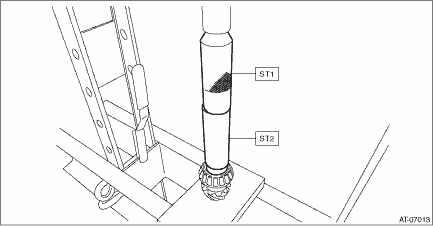
6. Using the ST1 and ST2, press-fit the inner race to the drive pinion shaft.
| ST1 899580100 | INSTALLER |
| ST2 927130000 | EXTENSION DRIVE SHAFT |
7. Install the drive pinion spacer.
NOTE:
Replace the O-ring with a new part after tooth contact inspection.
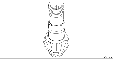
8. Install the selected drive pinion washer.
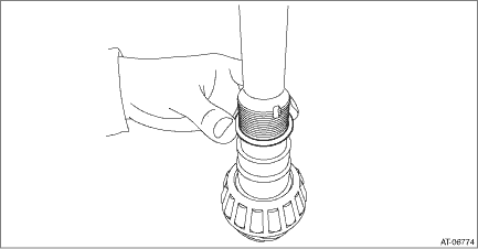
9. Insert the drive pinion shaft into the drive pinion retainer.
CAUTION:
Be careful not to damage the oil seal.
10. Install the inner bearing and lock nut.
NOTE:
• Use a new lock nut.
• Apply differential gear oil to the threaded portion of the drive pinion shaft.
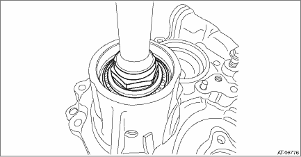
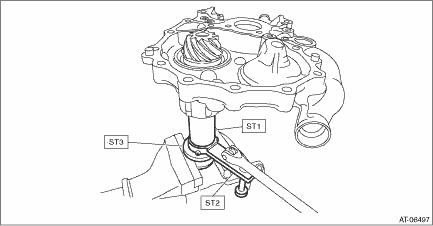
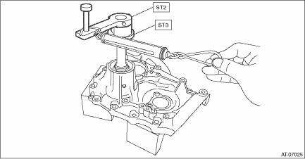
11. Using the ST, tighten the lock nut to the specified torque so that the starting torque of the drive pinion shaft is within the specified range.
CAUTION:
Before inspecting the starting torque, apply differential gear oil to roller of bearing and rotate the bearing several times.
NOTE:
• Tighten the lock nut while directly aligning ST2 and torque wrench.
• If the starting torque is not within the specified range, select the drive pinion washer, and repeat the step until the starting torque is within the specified range.
• When a thicker drive pinion washer is selected, the starting torque decreases. When a thinner drive pinion washer is selected, the starting torque increases.
Starting torque:
5.1 — 17.1 N (0.5 — 1.7 kgf, 1.1 — 3.8 lbf)
| ST1 499787500 | ADAPTER |
| ST2 499787700 | WRENCH |
| ST3 498937110 | HOLDER |
Using the following formula, calculate the tightening torque for a torque wrench.
T2 = L2/(L1 + L2) ? T1
T1: 170 — 250 N·m (17.3 — 25.5 kgf-m, 125.4 — 184.4 ft-lb) [Specified tightening torque range]
T2: Tightening torque
L1: ST1 length 0.072 m (2.83 in)
L2: Torque wrench length
Example:
Torque wrench length m (in) | Tightening torque N·m (kgf-m, ft-lb) |
0.4 (15.75) | 144 — 211 (14.7 — 21.5, 106.2 — 155.6) |
0.45 (17.72) | 147 — 215 (15.0 — 21.9, 108.4 — 158.6) |
0.5 (19.69) | 149 — 218 (15.2 — 22.2, 109.9 — 160.8) |
0.55 (21.65) | 150 — 221 (15.3 — 22.5, 110.6 — 163.0) |
12. Install the drive pinion retainer to the converter case, and check the backlash and tooth contact. Drive Pinion Shaft Assembly > ADJUSTMENT"> Front Differential Assembly > ADJUSTMENT">
13. Remove the drive pinion retainer from converter case. Drive Pinion Shaft Assembly > REMOVAL">
14. Remove the drive pinion spacer from the drive pinion shaft. Drive Pinion Shaft Assembly > DISASSEMBLY">
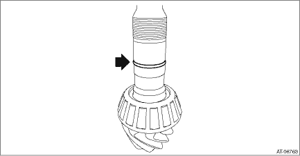
15. Install the O-ring to the drive pinion shaft.
NOTE:
• Use new O-rings.
• Apply CVTF to the O-rings.
16. Install the drive pinion spacer to the drive pinion shaft.

17. Install the drive pinion washer.

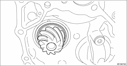
18. Insert the drive pinion shaft into the drive pinion retainer.
CAUTION:
Be careful not to damage the oil seal.
19. Install the inner bearing and lock nut.
NOTE:
Apply differential gear oil to the threaded portion of the drive pinion shaft.

20. Using the ST, tighten the lock nut to the specified torque so that the starting torque of the drive pinion shaft is within the specified range.
CAUTION:
Before inspecting the starting torque, apply differential gear oil to roller of bearing and rotate the bearing several times.
NOTE:
• Tighten the lock nut while directly aligning ST2 and torque wrench.
• If the starting torque is not within the specified range, select the drive pinion washer, and repeat the step until the starting torque is within the specified range.
• When a thicker drive pinion washer is selected, the starting torque decreases. When a thinner drive pinion washer is selected, the starting torque increases.
Starting torque:
5.1 — 17.1 N (0.5 — 1.7 kgf, 1.1 — 3.8 lbf)
| ST1 499787500 | ADAPTER |
| ST2 499787700 | WRENCH |
| ST3 498937110 | HOLDER |
Using the following formula, calculate the tightening torque for a torque wrench.
T2 = L2/(L1 + L2) ? T1
T1: 170 — 250 N·m (17.3 — 25.5 kgf-m, 125.4 — 184.4 ft-lb) [Specified tightening torque range]
T2: Tightening torque
L1: ST1 length 0.072 m (2.83 in)
L2: Torque wrench length
Example:
Torque wrench length m (in) | Tightening torque N·m (kgf-m, ft-lb) |
0.4 (15.75) | 144 — 211 (14.7 — 21.5, 106.2 — 155.6) |
0.45 (17.72) | 147 — 215 (15.0 — 21.9, 108.4 — 158.6) |
0.5 (19.69) | 149 — 218 (15.2 — 22.2, 109.9 — 160.8) |
0.55 (21.65) | 150 — 221 (15.3 — 22.5, 110.6 — 163.0) |


21. Crimp the lock nut in 2 locations.
22. Using the ST, install the plug.
| ST1 499755602 | PRESS SNAP RING |
| ST2 398177700 | INSTALLER |
 Removal
CONTINUOUSLY VARIABLE TRANSMISSION(TR580) > Drive Pinion Shaft AssemblyREMOVAL1. Remove the transmission assembly from the vehicle. Automatic Transmission Assembly > REMOVAL">2. Remove ...
 Disassembly
CONTINUOUSLY VARIABLE TRANSMISSION(TR580) > Drive Pinion Shaft AssemblyDISASSEMBLY1. Flatten the tab of the lock nut.2. Using ST1, ST2 and ST3, fix at the spline portion of drive pinion shaft to re ...
Other materials:
Caution
MECHANICAL(H4DO) > General DescriptionCAUTION• Prior to starting work, pay special attention to the following:1. Always wear work clothes, a work cap, and protective shoes. Additionally, wear a helmet, protective goggles, etc. if necessary.2. Protect the vehicle using a seat cover, fender c ...
Adjustment
CONTINUOUSLY VARIABLE TRANSMISSION(TR580) > CVTFADJUSTMENTCAUTION:• CVTF level changes along with CVTF temperature. When inspecting CVTF level, observe the specified CVTF temperature.• Always use specified CVTF. Using other fluid will cause malfunction.1. Idle the engine to raise CVTF ...
Electronic Brake Force Distribution
(EBD) system warning
The brake system warning light also
illuminates if a malfunction occurs in the
EBD system. In that event, it illuminates
together with the ABS warning light.
The EBD system may be malfunctioning if
the brake system warning light and ABS
warning light illuminate simultaneously
during driving ...
