Subaru Crosstrek Service Manual: Removal
CONTINUOUSLY VARIABLE TRANSMISSION(TR580) > Drive Pinion Shaft Assembly
REMOVAL
1. Remove the transmission assembly from the vehicle. Automatic Transmission Assembly > REMOVAL">
2. Remove the air breather hose. Air Breather Hose > REMOVAL">
3. Remove the control valve body. Control Valve Body > REMOVAL">
4. Remove the transmission harness. Transmission Harness > REMOVAL">
5. Remove the turbine speed sensor. Turbine Speed Sensor > REMOVAL">
6. Remove the secondary speed sensor. Secondary Speed Sensor > REMOVAL">
7. Remove the primary speed sensor. Primary Speed Sensor > REMOVAL">
8. Remove the inhibitor switch. Inhibitor Switch > REMOVAL">
9. Remove the extension case. Extension Case > REMOVAL">
10. Remove the transfer clutch assembly. Transfer Clutch > REMOVAL">
11. Remove the transfer driven gear assembly. Transfer Driven Gear > REMOVAL">
12. Remove the parking pawl. Parking Pawl > REMOVAL">
13. Remove the reduction driven gear assembly. Reduction Driven Gear > REMOVAL">
14. Remove the oil pan and oil strainer. Oil Pan and Strainer > REMOVAL">
15. Remove the transmission control device. Transmission Control Device > REMOVAL">
16. Remove the transmission case. Transmission Case > REMOVAL">
17. Remove the reduction drive gear. Reduction Drive Gear > REMOVAL">
18. Remove the primary pulley, secondary pulley and variator chain. Primary Pulley and Secondary Pulley > REMOVAL">
19. Remove the reverse brake assembly. Reverse Brake Assembly > REMOVAL">
20. Remove the forward clutch assembly. Forward Clutch Assembly > REMOVAL">
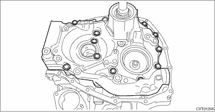
21. Using the ST, remove the drive pinion retainer.
| ST 18270KA020 | SOCKET (E20) |

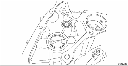
22. Remove the O-ring.

 Adjustment
CONTINUOUSLY VARIABLE TRANSMISSION(TR580) > Drive Pinion Shaft AssemblyADJUSTMENT1. Remove the liquid gasket from the mating surface completely.2. Using the ST, install the drive pinion retainer to ...
 Assembly
CONTINUOUSLY VARIABLE TRANSMISSION(TR580) > Drive Pinion Shaft AssemblyASSEMBLY1. Install the plug to drive pinion retainer.NOTE:• Use new O-rings.• Apply CVTF to the O-rings.Tightening ...
Other materials:
Inspection
CONTINUOUSLY VARIABLE TRANSMISSION(TR580) > Inhibitor SwitchINSPECTIONWhen the driving condition or starter motor operation is improper, first check the shift linkage for improper operation. If the shift linkage is functioning properly, check the inhibitor switch.1. Remove the clip (A) from the a ...
Component
SEATS > General DescriptionCOMPONENT1. FRONT SEAT• Manual seat LH(1)Pad ASSY - front seat backrest(15)Cover - hinge front seat OUT(29)Pad ASSY - front seat cushion(2)Cover COMPL - front backrest(16)Lever - reclining(30)Heater unit - front seat backrest(3)Cover - silencer front seat backrest ...
PIN Code Access (models with "keyless access with push-button start system")
Rear lock button
While all doors (including the rear gate)
are locked, you can unlock the doors
(including the rear gate) without a key by
pressing the rear lock button.
NOTE
PIN Code Access will be helpful if the
key is accidentally left in the vehicle. It
is recommended that a 5-d ...
