
Subaru Crosstrek Service Manual: System block diagram
Blind Spot Detection/Rear Cross Traffic Alert (DIAGNOSTICS) > Control Module I/O Signal
SYSTEM BLOCK DIAGRAM
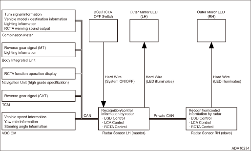
• Blind Spot Detection/Rear Cross Traffic Alert system consists of the following.
• There is a control ECM in the radar sensor main body, which performs the vehicle identification and the alert judgment control.
• The LH/RH radar sensors are identified as Master/Slave for control purposes. They are connected by the private CAN to execute the controls through mutual communication. The radar on the Master side receives the input from the vehicle CAN and the SRVD OFF switch, and information necessary for control can be obtained from other modules via the vehicle CAN.
• The outer mirror LED is directly driven by the signal from the radar sensor.
 Electrical specification
Blind Spot Detection/Rear Cross Traffic Alert (DIAGNOSTICS) > Control Module I/O SignalELECTRICAL SPECIFICATION1. RADAR SENSORTerminal No.ContentMeasuring conditionStandardRadar sensor LH (master)R ...
 Wiring diagram
Blind Spot Detection/Rear Cross Traffic Alert (DIAGNOSTICS) > Control Module I/O SignalWIRING DIAGRAMRefer to “BSD/RCTA System” in the wiring diagram. Blind Spot Detection/Rear Cross T ...
Other materials:
Operation
BODY CONTROL SYSTEM (DIAGNOSTICS) > Read Current DataOPERATION1. On «Start» display, select «Diagnosis».2. On «Vehicle selection» display, input the target vehicle information and select «Confirmed».3. On «Main Menu» display, select «Each System».4. On «Select System» display, selec ...
Dtc p0451 evap system (cpc) pressure sensor/switch circuit range/performance
ENGINE (DIAGNOSTICS)(H4DO) > Diagnostic Procedure with Diagnostic Trouble Code (DTC)DTC P0451 EVAP SYSTEM (CPC) PRESSURE SENSOR/SWITCH CIRCUIT RANGE/PERFORMANCEDTC detecting condition:Detected when two consecutive driving cycles with fault occur.CAUTION:After servicing or replacing faulty parts, ...
Note
WIPER AND WASHER SYSTEMS > Wiper and Washer SystemNOTEFor procedure of each component of the wiper and washer system, refer to the respective sections.• Combination switch (wiper): Combination Switch (Wiper)">• Wiper blade: Wiper Blade">• Front wiper arm: Fron ...
