Subaru Crosstrek Service Manual: Starter motor circuit
ENGINE (DIAGNOSTICS)(H4DO) > Diagnostics for Engine Starting Failure
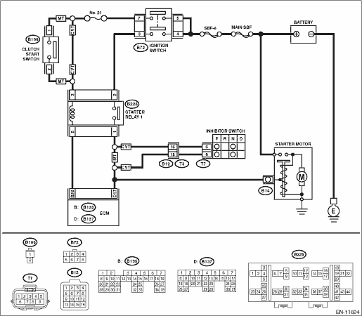
STARTER MOTOR CIRCUIT
1. MODEL WITHOUT PUSH BUTTON START
CAUTION:
After servicing or replacing faulty parts, perform Clear Memory Mode Clear Memory Mode"> , and Inspection Mode Inspection Mode">.
Wiring diagram:
Engine electrical system Engine Electrical System">
| STEP | CHECK | YES | NO |
1.CHECK BATTERY.
Check the battery. Battery">
Is the check result OK?
Diagnostics for Engine Starting Failure > STARTER MOTOR CIRCUIT">Go to Step 2.
Charge or replace the battery. Battery">
2.CHECK OPERATION OF STARTER MOTOR.
Does the starter motor operate?
Diagnostics for Engine Starting Failure > STARTER MOTOR CIRCUIT">Go to Step 3.
Diagnostics for Engine Starting Failure > STARTER MOTOR CIRCUIT">Go to Step 4.
3.CHECK DTC.
Are any DTCs displayed? Read Diagnostic Trouble Code (DTC) > OPERATION">
Check the appropriate DTC using the “List of Diagnostic Trouble Code (DTC)”. List of Diagnostic Trouble Code (DTC)">
Check ignition control system. Diagnostics for Engine Starting Failure > IGNITION CONTROL SYSTEM">
4.CHECK INPUT SIGNAL FOR STARTER MOTOR.
1) Turn the ignition switch to OFF.
2) Disconnect the connector from starter motor.
3) Turn the ignition switch to START.
4) Measure the voltage between the starter motor connector and the engine ground.
Connector & terminal
(B14) No. 1 (+) — Engine ground (−):
NOTE:
• For CVT model, place the select lever in “P” range or “N” range.
• For MT model, depress the clutch pedal.
Is the voltage 10 V or more?
Check the starter motor. Starter">
Diagnostics for Engine Starting Failure > STARTER MOTOR CIRCUIT">Go to Step 5.
5.CHECK HARNESS BETWEEN BATTERY AND IGNITION SWITCH CONNECTOR.
1) Turn the ignition switch to OFF.
2) Disconnect the connector from ignition switch.
3) Measure the power supply voltage between ignition switch connector and chassis ground.
Connector & terminal
(B72) No. 4 (+) — Chassis ground (−):
(B72) No. 5 (+) — Chassis ground (−):
Is the voltage 10 V or more?
Diagnostics for Engine Starting Failure > STARTER MOTOR CIRCUIT">Go to Step 6.
Repair the power supply circuit.
6.CHECK IGNITION SWITCH.
Measure the resistance between ignition switch terminals after turning the ignition switch to START position.
Terminals
No. 3 — No. 4:
No. 5 — No. 7:
Is the resistance less than 1 ??
Diagnostics for Engine Starting Failure > STARTER MOTOR CIRCUIT">Go to Step 7.
Replace the ignition switch. Ignition Key Lock > REPLACEMENT">
7.CHECK INPUT VOLTAGE OF STARTER RELAY 1.
1) Turn the ignition switch to OFF.
2) Remove the starter relay 1.
3) Connect the connector to ignition switch.
4) Measure the voltage between starter relay 1 connector and chassis ground after turning the ignition switch to START position.
Connector & terminal
(B225) No. 2 (+) — Chassis ground (−):
Is the voltage 10 V or more?
Diagnostics for Engine Starting Failure > STARTER MOTOR CIRCUIT">Go to Step 8.
Repair the open circuit of harness between starter relay 1 and ignition switch connector.
8.CHECK HARNESS BETWEEN ECM AND STARTER RELAY 1 CONNECTOR.
1) Turn the ignition switch to OFF.
2) Disconnect the connector from ECM.
3) Measure the resistance of harness between ECM connector and starter relay 1 connector.
Connector & terminal
(B135) No. 26 — (B225) No. 5:
Is the resistance less than 1 ??
Diagnostics for Engine Starting Failure > STARTER MOTOR CIRCUIT">Go to Step 9.
Repair the open circuit of harness between ECM connector and starter relay 1 connector.
9.CHECK STARTER RELAY 1.
1) Connect the battery to starter relay 1 terminals No. 3 and No. 5.
2) Measure the resistance between starter relay 1 terminals.
Terminals
No. 1 — No. 2:
Is the resistance less than 1 ??
Diagnostics for Engine Starting Failure > STARTER MOTOR CIRCUIT">Go to Step 10.
Replace the starter relay 1. Electrical Component Location">
10.CHECK TRANSMISSION TYPE.
Is the transmission type CVT?
Diagnostics for Engine Starting Failure > STARTER MOTOR CIRCUIT">Go to Step 11.
Diagnostics for Engine Starting Failure > STARTER MOTOR CIRCUIT">Go to Step 15.
11.CHECK INPUT VOLTAGE OF STARTER RELAY 1.
Measure the voltage between starter relay 1 connector and chassis ground after turning the ignition switch to START position.
Connector & terminal
(B225) No. 3 (+) — Chassis ground (−):
Is the voltage 10 V or more?
Diagnostics for Engine Starting Failure > STARTER MOTOR CIRCUIT">Go to Step 12.
Check the following item and repair if necessary.
• Blown out of fuse
• Open or short circuit to ground in harness between starter relay 1 and ignition switch connector
12.CHECK HARNESS BETWEEN STARTER RELAY 1 AND INHIBITOR SWITCH CONNECTOR.
1) Turn the ignition switch to OFF.
2) Disconnect the connector from inhibitor switch.
3) Measure the resistance of harness between starter relay 1 connector and inhibitor switch connector.
Connector & terminal
(B225) No. 1 — (T7) No. 6:
Is the resistance less than 1 ??
Diagnostics for Engine Starting Failure > STARTER MOTOR CIRCUIT">Go to Step 13.
Repair the harness and connector.
NOTE:
In this case, repair the following item:
• Open circuit in harness between starter relay 1 connector and inhibitor switch connector
• Poor contact of coupling connector
13.CHECK HARNESS BETWEEN INHIBITOR SWITCH AND STARTER MOTOR.
Measure the resistance of harness between the inhibitor switch connector and starter motor.
Connector & terminal
(T7) No. 9 — (B14) No. 1:
Is the resistance less than 1 ??
Diagnostics for Engine Starting Failure > STARTER MOTOR CIRCUIT">Go to Step 14.
Repair the harness and connector.
NOTE:
In this case, repair the following item:
• Open circuit in harness between inhibitor switch connector and starter motor
• Poor contact of coupling connector
14.CHECK INHIBITOR SWITCH.
1) Place the select lever in “P” range and “N” range.
2) Measure the resistance between inhibitor switch terminals.
Terminals
No. 6 — No. 9:
Is the resistance less than 1 ??
Check the engine control module (ECM) power supply and ground line. Diagnostics for Engine Starting Failure > CHECK POWER SUPPLY AND GROUND LINE OF ENGINE CONTROL MODULE (ECM)">
Replace the inhibitor switch. Inhibitor Switch">
15.CHECK INPUT VOLTAGE OF CLUTCH START SWITCH.
1) Disconnect the connector from clutch start switch.
2) Turn the ignition switch to START.
3) Measure the voltage between the clutch start switch connector and chassis ground.
Connector & terminal
(B106) No. 1 (+) — Chassis ground (−):
Is the voltage 10 V or more?
Diagnostics for Engine Starting Failure > STARTER MOTOR CIRCUIT">Go to Step 16.
Check the following item and repair if necessary.
• Blown out of fuse
• Open or short circuit to ground in harness between ignition switch connector and clutch start switch connector
16.CHECK CLUTCH START SWITCH.
1) Turn the ignition switch to OFF.
2) Measure the resistance between clutch start switch terminals while keeping the clutch pedal depressed.
Terminals
No. 1 — No. 2:
Is the resistance less than 1 ??
Diagnostics for Engine Starting Failure > STARTER MOTOR CIRCUIT">Go to Step 17.
Replace the clutch start switch. Clutch Switch">
17.CHECK HARNESS BETWEEN STARTER RELAY 1 AND CLUTCH START SWITCH.
Measure the resistance of harness between starter relay 1 and clutch start switch connector.
Connector & terminal
(B225) No. 3 — (B106) No. 2:
Is the resistance less than 1 ??
Diagnostics for Engine Starting Failure > STARTER MOTOR CIRCUIT">Go to Step 18.
Repair the open circuit in harness between starter relay 1 and clutch start switch connector.
18.CHECK HARNESS BETWEEN STARTER RELAY 1 AND STARTER MOTOR.
Measure the resistance of harness between starter relay 1 connector and starter motor.
Connector & terminal
(B225) No. 1 — (B14) No. 1:
Is the resistance less than 1 ??
Check the engine control module (ECM) power supply and ground line. Diagnostics for Engine Starting Failure > CHECK POWER SUPPLY AND GROUND LINE OF ENGINE CONTROL MODULE (ECM)">
Repair the open circuit of the harness between starter relay 1 connector and starter motor.
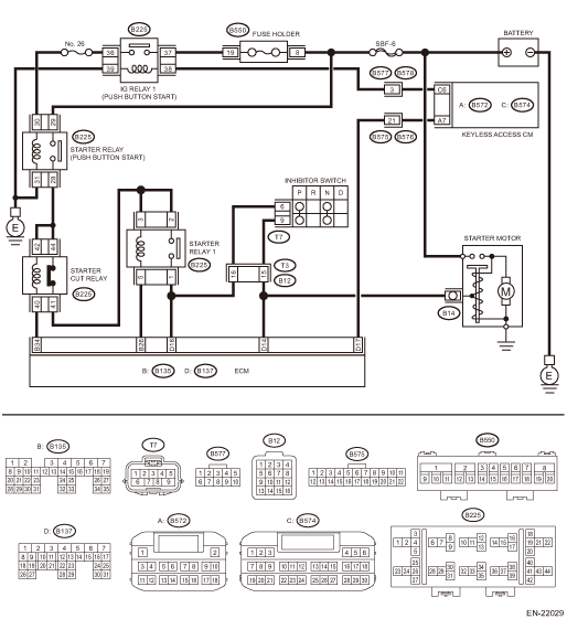
2. MODEL WITH PUSH BUTTON START
CAUTION:
After servicing or replacing faulty parts, perform Clear Memory Mode Clear Memory Mode">, and Inspection Mode Inspection Mode">.
Wiring diagram:
Engine electrical system Engine Electrical System">
| STEP | CHECK | YES | NO |
1.CHECK DTC.
Are any DTCs displayed? Read Diagnostic Trouble Code (DTC) > OPERATION">
Check the appropriate DTC using the “List of Diagnostic Trouble Code (DTC)”. List of Diagnostic Trouble Code (DTC)">
Diagnostics for Engine Starting Failure > STARTER MOTOR CIRCUIT">Go to Step 2.
2.CHECK NEUTRAL POSITION SWITCH SIGNAL.
1) Read the value of «Neutral Position Switch» using the Subaru Select Monitor.
NOTE:
For detailed operation procedures, refer to “Current Data Display For Engine”. Subaru Select Monitor">
2) Turn the ignition to ON.
3) Place the select lever in “P” range or “N” range.
Is «Neutral» displayed?
Diagnostics for Engine Starting Failure > STARTER MOTOR CIRCUIT">Go to Step 3.
Diagnostics for Engine Starting Failure > STARTER MOTOR CIRCUIT">Go to Step 8.
3.CHECK BATTERY.
Check the battery. Battery">
Is the check result OK?
Diagnostics for Engine Starting Failure > STARTER MOTOR CIRCUIT">Go to Step 4.
Charge or replace the battery. Battery">
4.CHECK OPERATION OF STARTER MOTOR.
Does the starter motor operate?
Check ignition control system. Diagnostics for Engine Starting Failure > IGNITION CONTROL SYSTEM">
Diagnostics for Engine Starting Failure > STARTER MOTOR CIRCUIT">Go to Step 5.
5.CHECK PUSH BUTTON IGNITION SWITCH.
Press the push button ignition switch twice with the ignition OFF (ACC OFF).
NOTE:
Release the brake pedal.
Does the ignition turn to ON?
Diagnostics for Engine Starting Failure > STARTER MOTOR CIRCUIT">Go to Step 6.
Check the push button start system. General Diagnostic Table > INSPECTION">
6.CHECK PUSH BUTTON IGNITION SWITCH.
1) Depress the brake pedal.
NOTE:
Shift the select lever to “P” range.
2) Check the push button ignition switch indicator.
Does the indicator turn to green?
Diagnostics for Engine Starting Failure > STARTER MOTOR CIRCUIT">Go to Step 7.
Check the push button start system. Diagnostics with Phenomenon > INSPECTION">
7.CHECK START SWITCH SIGNAL.
1) Read the waveform of «Starter Switch» using the Subaru Select Monitor.
NOTE:
For detailed operation procedures, refer to “Current Data Display For Engine”. Subaru Select Monitor">
2) Press the push button ignition switch once with the brake pedal depressed.
Does waveform of the «Starter Switch» occur?
Diagnostics for Engine Starting Failure > STARTER MOTOR CIRCUIT">Go to Step 11.
Diagnostics for Engine Starting Failure > STARTER MOTOR CIRCUIT">Go to Step 8.
8.CHECK HARNESS BETWEEN ECM AND KEYLESS ACCESS CM.
1) Turn the ignition to OFF.
2) Disconnect the connector from ECM.
3) Disconnect the connector from the keyless access CM.
4) Measure the resistance of harness between ECM connector and keyless access CM.
Connector & terminal
(B137) No. 17 — (B572) No. 7:
Is the resistance less than 1 ??
Diagnostics for Engine Starting Failure > STARTER MOTOR CIRCUIT">Go to Step 9.
Repair the harness and connector.
NOTE:
In this case, repair the following item:
• Open circuit of harness between ECM connector and keyless access CM connector
• Poor contact of coupling connector
9.CHECK HARNESS BETWEEN ECM AND KEYLESS ACCESS CM.
Measure the resistance between ECM connector and chassis ground.
Connector & terminal
(B137) No. 17 — Chassis ground:
Is the resistance 1 M? or more?
Diagnostics for Engine Starting Failure > STARTER MOTOR CIRCUIT">Go to Step 10.
Repair the short circuit to ground in harness between ECM connector and keyless access CM connector.
10.CHECK START SWITCH SIGNAL.
1) Connect the connector to ECM.
2) Connect the connector to the keyless access CM.
3) Read the waveform of start switch signal using an oscilloscope.
4) Press the push button ignition switch once with the brake pedal depressed.
Connector & terminal
(B137) No. 17 (+) — Chassis ground (−):
Does waveform of the start switch signal occur?
Repair the poor contact of ECM connector.
Repair the poor contact of keyless access CM connector.
11.CHECK INPUT SIGNAL FOR STARTER MOTOR.
1) Turn the ignition to OFF.
2) Disconnect the connector from starter motor.
3) Place the select lever in “P” range or “N” range.
4) Press the push button ignition switch once with the brake pedal depressed.
5) Measure the voltage between the starter motor connector and the engine ground.
Connector & terminal
(B14) No. 1 (+) — Engine ground (−):
Is the voltage 10 V or more?
Check the starter motor. Starter">
Diagnostics for Engine Starting Failure > STARTER MOTOR CIRCUIT">Go to Step 12.
12.CHECK HARNESS BETWEEN BATTERY AND STARTER MOTOR.
1) Turn the ignition to OFF.
2) Measure the voltage between starter motor terminal B and engine ground.
Terminals
Terminal B (+) — Engine ground (−):
Is the voltage 10 V or more?
Diagnostics for Engine Starting Failure > STARTER MOTOR CIRCUIT">Go to Step 13.
Repair the power supply circuit.
13.CHECK IG RELAY 1 (PUSH BUTTON START) POWER SUPPLY.
1) Remove the IG relay 1 (push button start).
2) Turn the ignition to ON.
3) Measure the voltage between the IG relay 1 (push button start) connector and chassis ground.
Connector & terminal
(B225) No. 37 (+) — Chassis ground (−):
(B225) No. 38 (+) — Chassis ground (−):
Is the voltage 10 V or more?
Diagnostics fo
 Check power supply and ground line of engine control module (ecm)
ENGINE (DIAGNOSTICS)(H4DO) > Diagnostics for Engine Starting FailureCHECK POWER SUPPLY AND GROUND LINE OF ENGINE CONTROL MODULE (ECM)CAUTION:After servicing or replacing faulty parts, perform Clear ...
 Procedure
ENGINE (DIAGNOSTICS)(H4DO) > Diagnostics for Engine Starting FailurePROCEDURE1. Check of the fuel amount↓2. Inspection of starter motor circuit Diagnostics for Engine Starting Failure > ST ...
Other materials:
Disassembly
GLASS/WINDOWS/MIRRORS > Outer Mirror AssemblyDISASSEMBLYCAUTION:When removing the mirror - repair, be careful not to damage the back surface of mirror - repair with a flat tip screwdriver.1. Operate the remote control mirror switch to face the mirror - repair upward.2. Disconnect the ground cable ...
Caution
REAR SUSPENSION > General DescriptionCAUTIONPlease clearly understand and adhere to the following general precautions. They must be strictly followed to avoid minor or serious injury to the person doing the work or people in the area.1. EACH PROCEDURE• Wear appropriate work clothing, includ ...
Selection of manual mode
In the Subaru Ascent, manual mode allows the driver to take direct control over
gear selection for a more engaging and responsive driving experience. Whether the
vehicle is stationary or in motion, you can activate this mode by moving the select
lever from the "D" (Drive) positio ...
