Subaru Crosstrek Service Manual: Check power supply and ground line of engine control module (ecm)
ENGINE (DIAGNOSTICS)(H4DO) > Diagnostics for Engine Starting Failure
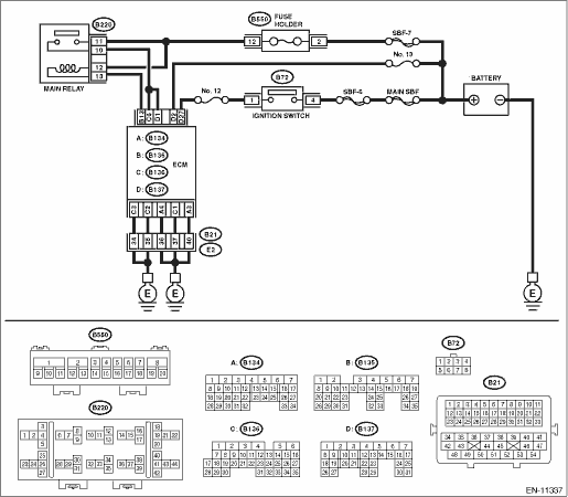
CHECK POWER SUPPLY AND GROUND LINE OF ENGINE CONTROL MODULE (ECM)
CAUTION:
After servicing or replacing faulty parts, perform Clear Memory Mode Clear Memory Mode > OPERATION"> , and Inspection Mode Inspection Mode > PROCEDURE">.
WIRING DIAGRAM:
Engine electrical system Engine Electrical System">
| STEP | CHECK | YES | NO |
1.CHECK MAIN RELAY.
1) Turn the ignition switch to OFF.
2) Remove the main relay.
3) Connect the battery to main relay terminals No. 12 and No. 13.
4) Measure the resistance between main relay terminals.
Terminals
No. 10 — No. 11:
Is the resistance less than 1 ??
Diagnostics for Engine Starting Failure > CHECK POWER SUPPLY AND GROUND LINE OF ENGINE CONTROL MODULE (ECM)">Go to Step 2.
Replace the main relay. Main Relay">
2.CHECK GROUND CIRCUIT FOR ECM.
1) Disconnect the connector from ECM.
2) Measure the resistance of harness between ECM connector and chassis ground.
Connector & terminal
(B134) No. 3 — Chassis ground:
(B134) No. 4 — Chassis ground:
(B136) No. 1 — Chassis ground:
(B136) No. 2 — Chassis ground:
(B136) No. 3 — Chassis ground:
Is the resistance less than 5 ??
Diagnostics for Engine Starting Failure > CHECK POWER SUPPLY AND GROUND LINE OF ENGINE CONTROL MODULE (ECM)">Go to Step 3.
Repair the harness and connector.
NOTE:
In this case, repair the following item:
• Open circuit of harness between ECM connector and engine ground terminal
• Poor contact of coupling connector
3.CHECK INPUT VOLTAGE OF ECM.
1) Turn the ignition switch to ON.
2) Measure the voltage between ECM connector and chassis ground.
Connector & terminal
(B137) No. 2 (+) — Chassis ground (−):
(B137) No. 27 (+) — Chassis ground (−):
Is the voltage 10 V or more?
Diagnostics for Engine Starting Failure > CHECK POWER SUPPLY AND GROUND LINE OF ENGINE CONTROL MODULE (ECM)">Go to Step 4.
Repair the open or ground short circuit of harness of power supply circuit.
4.CHECK INPUT VOLTAGE OF MAIN RELAY.
Measure the voltage between main relay connector and chassis ground.
Connector & terminal
(B220) No. 11 (+) — Chassis ground (−):
(B220) No. 12 (+) — Chassis ground (−):
Is the voltage 10 V or more?
Diagnostics for Engine Starting Failure > CHECK POWER SUPPLY AND GROUND LINE OF ENGINE CONTROL MODULE (ECM)">Go to Step 5.
Repair the open or ground short circuit of harness of power supply circuit.
5.CHECK INPUT VOLTAGE OF ECM.
1) Turn the ignition switch to OFF.
2) Install the main relay.
3) Turn the ignition switch to ON.
4) Measure the voltage between ECM connector and chassis ground.
Connector & terminal
(B135) No. 13 (+) — Chassis ground (−):
Is the voltage 10 V or more?
Diagnostics for Engine Starting Failure > CHECK POWER SUPPLY AND GROUND LINE OF ENGINE CONTROL MODULE (ECM)">Go to Step 6.
Repair the open circuit of harness between ECM connector and main relay connector.
6.CHECK INPUT VOLTAGE OF ECM.
1) Turn the ignition switch to OFF.
2) Connect the connector to ECM.
3) Turn the ignition switch to ON.
4) Measure the voltage between ECM connector and chassis ground.
Connector & terminal
(B136) No. 6 (+) — Chassis ground (−):
(B137) No. 1 (+) — Chassis ground (−):
Is the voltage 10 V or more?
Check ignition control system. Diagnostics for Engine Starting Failure > IGNITION CONTROL SYSTEM">
Repair the harness and connector.
NOTE:
In this case, repair the following item:
• Open circuit in harness between ECM connector and main relay connector
• Poor contact of main relay connector
• Poor contact of ECM connector

 Starter motor circuit
ENGINE (DIAGNOSTICS)(H4DO) > Diagnostics for Engine Starting FailureSTARTER MOTOR CIRCUIT1. MODEL WITHOUT PUSH BUTTON STARTCAUTION:After servicing or replacing faulty parts, perform Clear Memory Mo ...
Other materials:
Assembly
COOLING(H4DO) > Radiator Sub Fan and Fan MotorASSEMBLYAssemble in the reverse order of disassembly.Tightening torque:4.41 N·m (0.45 kgf-m, 3.25 ft-lb)Tightening torque:3.4 N·m (0.3 kgf-m, 2.5 ft-lb) ...
Blind spot detection/rear cross traffic alert
Note
Blind Spot Detection/Rear Cross Traffic Alert > Blind Spot Detection/Rear Cross Traffic AlertNOTEFor procedure of each component in the Subaru Rear Vehicle Detection system, refer to the respective sections.• Radar sensor: Radar Sensor">• BSD/RCTA OFF switch: Switches ...
Dtc c1221 front left abs sensor circuit
VEHICLE DYNAMICS CONTROL (VDC) (DIAGNOSTICS) > Diagnostic Procedure with Diagnostic Trouble Code (DTC)DTC C1221 FRONT LEFT ABS SENSOR CIRCUITNOTE:For the diagnostic procedure, refer to “DTC C1241 REAR LEFT ABS SENSOR CIRCUIT”. Diagnostic Procedure with Diagnostic Trouble Code (DTC) & ...
