Subaru Crosstrek Service Manual: Specification
HVAC SYSTEM (HEATER, VENTILATOR AND A/C) > General Description
SPECIFICATION
1. HEATER SYSTEM
Item | Specifications | Condition | |
Heating capacity | 5.0 kW (4,299 kcal/h, 17,059 BTU/h) or more | ||
• Air flow control dial or switch: FOOT
• Temperature control dial: HI (MAX HOT)
• Temperature difference between hot water and inlet air: 65°C (149°F)
• Hot water flow rate: 360 L (95.1 US gal, 79.2 Imp gal)/h
Air flow rate
290 m3 (10,243 cu ft)/h
FOOT mode (FRESH), MAX HOT at 12.5 V
Max air flow rate
480 m3 (16,954 cu ft)/h
• Temperature control dial: LO (MAX COOL)
• Fan dial: HI (MAX)
Auto A/C model: 7th position
Manual A/C model: 4th position
• FRESH/RECIRC switch: RECIRC
Heater core
Dimensions (W ? H ? T)
257.5 ? 118.5 ? 27 mm
(10.1 ? 4.67 ? 1.06 in)
—
Blower motor
Type
Magnet motor 300 W or less
12 V
Fan type and size
(diameter ? width)
Sirocco fan type
150 ? 75 mm (5.91 ? 2.95 in)
—
2. A/C SYSTEM
Item | Specifications | ||
Type of air conditioner | Reheat air-mix type | ||
Cooling capacity | 5.0 kW (4,299 kcal/h, 17,059 BTU/h) | ||
Refrigerant | HFC-134a (CH2 FCF3) [0.475±0.025 kg (1.05±0.06 lb)] | ||
Compressor | Type | Rotary fixed capacity (DKV-10Z) | |
Discharge | 105 cc (6.41 cu in)/rev | ||
Max. permissible speed | 7,700 r/min | ||
Magnet clutch | Type | Dry, single-disc type | |
Power consumption | 45 W | ||
Type of belt | V-belt 6 PK | ||
Pulley dia. (effective dia.) | 110 mm (4.33 in) | ||
Pulley ratio | 1.3 | ||
Condenser | Type | Sub cool type | |
Core face area | 0.188 m2 (2.002 sq ft) | ||
Core thickness | 16 mm (0.63 in) | ||
Radiation area | 4.5 m2 (48.44 sq ft) | ||
Expansion valve | Type | Block | |
Evaporator | Type | Dual-tank | |
Dimensions (W ? H ? T) | 290.1 ? 172 ? 39 mm (11.42 ? 6.77 ? 1.54 in) | ||
Blower fan | Fan type | Sirocco fan | |
Outer diameter ? Width | 150 ? 75 mm (5.91 ? 2.95 in) | ||
Power consumption | 280 W | ||
Condenser fan (sub fan) | Motor type | Magnet | |
Power consumption | 120 W | ||
Fan outer diameter | 320 mm (12.6 in) | ||
Radiator fan (main fan) | Motor type | Magnet | |
Power consumption | 120 W | ||
Fan outer diameter | 320 mm (12.6 in) | ||
Idle speed | No load | 650±100 r/min | |
A/C ON | 800 — 900±50 r/min | ||
Triple switch (Pressure switch) | Low-pressure switch operating pressure | ON > OFF | 196±25 kPa (2.00±0.25 kgf/cm2, 28.4±3.6 psi) |
OFF > ON | 225±30 kPa (2.29±0.31 kgf/cm2, 32.6±4.3 psi) | ||
High-pressure switch operating pressure | ON > OFF | 2,940±200 kPa (29.98±2.04 kgf/cm2, 426.3±29 psi) | |
OFF > ON | 2,350±200 kPa (24.00±2.04 kgf/cm2, 340.7±29.0 psi) | ||
Middle-pressure switch operating pressure | ON > OFF | 1,470±120 kPa (14.99±1.22 kgf/cm2, 213.15±17.4 psi) | |
OFF > ON | 1,770±100 kPa (18.05±1.02 kgf/cm2, 256.65±14.5 psi) | ||
Thermo-control amplifier working temperature | |||
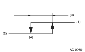
(1) ON
(2) OFF
(3) 1.5±0.3°C (34.7±0.5°F)
(4) 1.0±0.5°C (33.8±0.9°F)
3. BASIC OPERATION
The cooling system cools down the compartment by using the pipes connecting parts and cycling the evaporable liquid (refrigerant) within the sealed system in a repeated process of “vaporization — liquefaction — re-vaporization”.
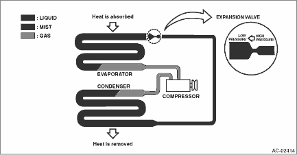
Item | Operation |
Compressor | Sucks and pressurizes the low temperature, low pressure refrigerant gas that was vaporized at the evaporator by absorbing heat from the compartment, and sends the high temperature, high pressure refrigerant gas to the condenser. |
Condenser | Cools the high temperature, high pressure refrigerant gas sent from the compressor for condense and liquefaction. |
Expansion valve |
• Sprays the high temperature, high pressure liquid refrigerant from the small hole in order to let the refrigerant expand rapidly to turn it into low temperature, low pressure mist.
• The refrigerant amount is adjusted according to the refrigerant vaporization condition in the evaporator.
Evaporator
The evaporator turns into a low temperature condition when the mist refrigerant that was turned into a low temperature, low pressure condition at the expansion valve is vaporized in large quantity in the evaporator. Passing air flow through the low temperature evaporator emits cold air.
 Caution
HVAC SYSTEM (HEATER, VENTILATOR AND A/C) > General DescriptionCAUTION• Before disassembling or reassembling parts, always disconnect the battery ground cable from battery. When replacing the ...
 Component
HVAC SYSTEM (HEATER, VENTILATOR AND A/C) > General DescriptionCOMPONENT1. HEATER AND COOLING UNIT• Manual A/C model(1)Pipe - inlet(11)Shutter - defroster(21)Packing - evaporator core(2)Pipe - ...
Other materials:
Using a flat-bed truck
This is the best way to transport your
vehicle. Use the following procedures to
ensure safe transportation.
1. Shift the select lever into the "P" position for CVT models. Shift the shift
lever into the "1st" position for MT models.
2. Pull up the parking brake lever firmly.
3. Secur ...
Subaru select monitor Operation
HVAC SYSTEM (AUTO A/C) (DIAGNOSTICS) > Subaru Select MonitorOPERATIONFor detailed operation procedures, refer to “Application help”.NOTE:When initialization communication using Select Monitor is impossible, perform diagnosis according to “Diagnostic Procedure Used When Abnormal ...
Dtc c0062 normal opening valve 2 malfunction
VEHICLE DYNAMICS CONTROL (VDC) (DIAGNOSTICS) > Diagnostic Procedure with Diagnostic Trouble Code (DTC)DTC C0062 NORMAL OPENING VALVE 2 MALFUNCTIONNOTE:For the diagnostic procedure, refer to “C0064 NORMAL CLOSING VALVE 2 MALFUNCTION”. Diagnostic Procedure with Diagnostic Trouble Code ...
