Subaru Crosstrek Service Manual: Component
HVAC SYSTEM (HEATER, VENTILATOR AND A/C) > General Description
COMPONENT
1. HEATER AND COOLING UNIT
• Manual A/C model
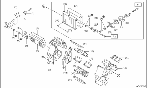
(1) | Pipe - inlet | (11) | Shutter - defroster | (21) | Packing - evaporator core |
(2) | Pipe - outlet | (12) | Shutter - vent | (22) | Pipe - evaporator core |
(3) | Clamp - pipe | (13) | Shutter - air mix RH | (23) | Case - expansion valve |
(4) | Seal O-ring | (14) | Shutter - air mix LH | (24) | Seal - cooling |
(5) | Clamp | (15) | Guide - heater unit | (25) | Packing - heater unit |
(6) | Plate - heater core | (16) | Shutter - foot | (26) | Expansion valve - cooling |
(7) | Packing - heater core | (17) | Case - vent duct | ||
(8) | Heater core | (18) | Case - heater unit UPR RH | Tightening torque: N·m (kgf-m, ft-lb) | |
(9) | Case - heater unit UPR LH | (19) | Thermostat - cooling | T1: | 5.0 (0.51, 3.7) |
(10) | Plate CTR | (20) | Evaporator ASSY - cooling | T2: | 6.7 (0.68, 4.9) |
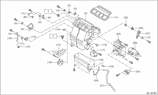
(1) | Packing - heater unit | (11) | Clip | (21) | Hose - drain |
(2) | Case - heater unit | (12) | Lever - foot | (22) | Resistor |
(3) | Lever - defroster | (13) | Lever - foot sub | (23) | Cover |
(4) | Lever - defroster sub | (14) | Clamp - cable | (24) | Cover - heater unit |
(5) | Washer - heater | (15) | Cover - heater pipe | (25) | Spring - heater unit |
(6) | Lever - ventilator sub | (16) | Duct - foot LH | (26) | Lever A |
(7) | Rod - ventilator | (17) | Duct - foot RH | (27) | Lever B |
(8) | Lever - ventilator door | (18) | Case - heater LWR | ||
(9) | Lever - mode | (19) | Clip - case | Tightening torque: N·m (kgf-m, ft-lb) | |
(10) | Rod - foot | (20) | Packing - evaporator cover | T: | 7.5 (0.76, 5.5) |
• Auto A/C model
(1) | Pipe - inlet | (11) | Shutter - defroster | (21) | Packing - evaporator core |
(2) | Pipe - outlet | (12) | Shutter - vent | (22) | Pipe - evaporator core |
(3) | Clamp - pipe | (13) | Shutter - air mix RH | (23) | Case - expansion valve |
(4) | Seal O-ring | (14) | Shutter - air mix LH | (24) | Seal - cooling |
(5) | Clamp | (15) | Guide - heater unit | (25) | Packing - heater unit |
(6) | Plate - heater core | (16) | Shutter - foot | (26) | Expansion valve - cooling |
(7) | Packing - heater core | (17) | Case - vent duct | ||
(8) | Heater core | (18) | Case - heater unit UPR RH | Tightening torque: N·m (kgf-m, ft-lb) | |
(9) | Case - heater unit UPR LH | (19) | Thermostat - cooling | T1: | 5.0 (0.51, 3.7) |
(10) | Plate CTR | (20) | Evaporator ASSY - cooling | T2: | 6.7 (0.68, 4.9) |
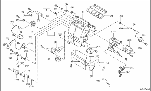
(1) | Packing - heater unit | (13) | Lever - foot sub | (25) | Spring - heater unit |
(2) | Case - heater unit | (14) | Harness - heater unit | (26) | Lever - air mix |
(3) | Lever - defroster | (15) | Cover - heater pipe | (27) | Rod - air mix |
(4) | Lever - defroster sub | (16) | Duct - foot LH | (28) | Motor - actuator mix RH |
(5) | Washer - heater | (17) | Duct - foot RH | (29) | Rod - mode |
(6) | Lever - ventilator sub | (18) | Case - heater LWR | (30) | Motor - actuator mode |
(7) | Rod - ventilator | (19) | Clip - case | (31) | Aspirator - heater unit |
(8) | Lever - ventilator door | (20) | Packing - evaporator cover | (32) | Aspirator hose |
(9) | Lever - mode | (21) | Hose - drain | (33) | Motor - actuator mix LH (dual A/C model) |
(10) | Rod - foot | (22) | Power transistor | ||
(11) | Clip | (23) | Cover | Tightening torque: N·m (kgf-m, ft-lb) | |
(12) | Lever - foot | (24) | Cover - heater unit | T: | 7.5 (0.76, 5.5) |
2. BLOWER MOTOR UNIT
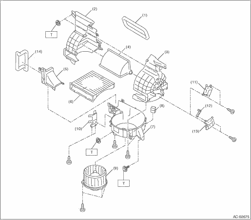
(1) | Packing - blower | (7) | Case lower - blower | (13) | Motor - actuator blower (manual A/C model) |
(2) | Case - blower intake LH | (8) | Blower motor relay | (14) | Packing |
(3) | Case - blower intake RH | (9) | Blower - motor | ||
(4) | Shutter - blower | (10) | Bracket | Tightening torque: N·m (kgf-m, ft-lb) | |
(5) | Case upper - blower | (11) | Motor - actuator blower (auto A/C model) | T: | 7.5 (0.76, 5.5) |
(6) | Filter kit | (12) | Lever | ||
3. CONTROL PANEL
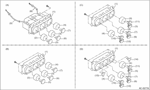
(A) | Manual A/C model | (C) | Single auto A/C model (with high grade MFD) | (D) | Dual auto A/C model |
(B) | Single auto A/C model (with standard MFD) | ||||
(1) | Control case | (6) | FRESH/RECIRC switch | (11) | Defroster switch |
(2) | Air flow control dial | (7) | A/C switch | (12) | OFF switch |
(3) | Fan dial | (8) | Temperature control cable | (13) | Air flow control switch |
(4) | Temperature adjustment dial | (9) | Air flow control cable | (14) | Dual switch |
(5) | Rear window defogger switch | (10) | AUTO switch |
4. AIR CONDITIONING UNIT
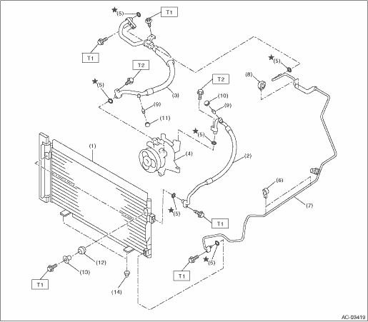
(1) | Condenser ASSY - air conditioner | (7) | Pipe - evaporator cooling | (13) | Spacer |
(2) | Hose - pressure discharge | (8) | Clip | (14) | Bushing - condenser |
(3) | Hose - pressure suction | (9) | Valve - hose pressure | ||
(4) | Compressor ASSY | (10) | Cap - hose pressure discharge | Tightening torque: N·m (kgf-m, ft-lb) | |
(5) | Seal O-ring | (11) | Cap - hose pressure suction | T1: | 7.5 (0.76, 5.5) |
(6) | Clip - pipe | (12) | Grommet | T2: | 10 (1.02, 7.4) |
5. HEATER HOSE
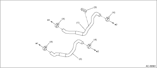
(1) | Hose - heater outlet | (3) | Clip | (4) | Clamp |
(2) | Hose - heater inlet | ||||
*1: Engine side *2: Heater core side | |||||
6. COMPRESSOR
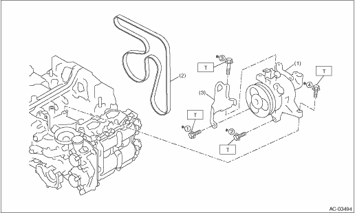
(1) | Compressor ASSY | (3) | Hanger - engine front | Tightening torque: N·m (kgf-m, ft-lb) | |
(2) | V-belt (6 PK) | T: | 36 (3.67, 26.6) | ||
*: Tighten the compressor in the numerical order as shown in the figure. | |||||
7. HEATER DUCT
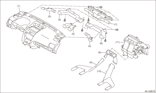
(1) | Panel COMPL - instrument | (5) | Duct - side defroster RH | (9) | Duct - rear heater LH |
(2) | Duct - side defroster LH | (6) | Duct - side ventilation RH | (10) | Duct - rear heater RH |
(3) | Duct - side ventilation LH | (7) | Nozzle - front defroster | (11) | Heater and cooling unit ASSY |
(4) | Duct - center vent | (8) | Duct - rear heater CTR |
 Specification
HVAC SYSTEM (HEATER, VENTILATOR AND A/C) > General DescriptionSPECIFICATION1. HEATER SYSTEMItemSpecificationsConditionHeating capacity5.0 kW (4,299 kcal/h, 17,059 BTU/h) or more• Air flow con ...
 Location
HVAC SYSTEM (HEATER, VENTILATOR AND A/C) > General DescriptionLOCATIONRefer to “LOCATION” for “HVAC SYSTEM (AUTO A/C) (DIAGNOSTICS)” section. Electrical Component Location ...
Other materials:
Assembly
DRIVE SHAFT SYSTEM > Rear AxleASSEMBLY1. BUSHING - REAR AXLE HOUSINGDo not remove the bushing - rear axle housing from the rear axle housing, because it cannot be replaced. If removed, replace the rear axle housing.2. REAR BUSHING1. Before assembly, inspect the following items and replace any fau ...
Removal
MANUAL TRANSMISSION AND DIFFERENTIAL(5MT) > Reverse Check SleeveREMOVAL1. Remove the manual transmission assembly from the vehicle. Manual Transmission Assembly > REMOVAL">2. Remove the transfer case together with the extension case assembly. Transfer Case and Extension Case Assembly ...
Dtc p0500 vehicle speed sensor "a" circuit
CONTINUOUSLY VARIABLE TRANSMISSION (DIAGNOSTICS) > Diagnostic Procedure with Diagnostic Trouble Code (DTC)DTC P0500 VEHICLE SPEED SENSOR "A" CIRCUITDTC DETECTING CONDITION:Immediately at fault recognitionTROUBLE SYMPTOM:VDC does not operate.STEPCHECKYESNO1.CHECK DTC.Read the DTC of VDC ...
