Subaru Crosstrek Service Manual: Removal
REAR SUSPENSION > Rear Shock Absorber
REMOVAL
1. CROSSTREK MODEL
1. Disconnect the ground cable from battery. NOTE">
2. Lift up the vehicle, and then remove the rear wheels.
3. Remove the sensor assembly - headlight beam leveler. (Model with auto headlight beam leveler, left side only)
CAUTION:
Do not apply impact to the sensor assembly - headlight beam leveler or forcibly move the arm. Doing so may cause sensor damage and malfunction.
(1) Disconnect the connector of the sensor assembly - headlight beam leveler.
(2) Remove the nuts, and remove the sensor assembly - headlight beam leveler.
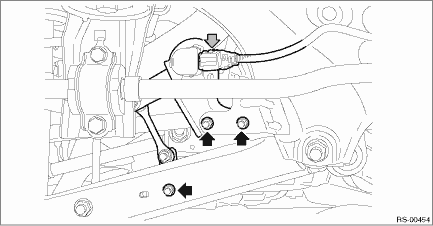
4. Remove the bolts and nuts, and lower the lateral link assembly - rear.
(1) Remove the nut and disconnect the rear stabilizer link. (Model with rear stabilizer)
(2) Remove the bolts from the lower side of rear shock absorber assembly.
(3) Disconnect the housing assembly - rear axle from the lateral link assembly - rear.
5. Remove the mat - rear floor CTR and the spacer - rear floor side.
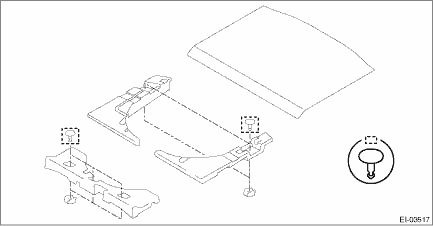
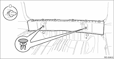
6. Remove the clips, and remove the trim panel - rear skirt.
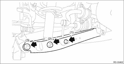
7. Remove the lid upper rear (a) and the cap - rear strut (b) in the order from (1) to (6).
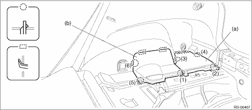
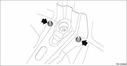
8. Remove the nuts on the upper side of rear shock absorber assembly.
9. Lower the lateral link assembly - rear, and remove the rear shock absorber assembly.
 Assembly
REAR SUSPENSION > Rear Shock AbsorberASSEMBLY1. Before assembly, check each part. Rear Shock Absorber > INSPECTION">2. Using a coil spring compressor, compress the coil spring - rear.CA ...
 Disassembly
REAR SUSPENSION > Rear Shock AbsorberDISASSEMBLY1. Using a coil spring compressor, compress the coil spring.2. Using a hexagon wrench to prevent the shock absorber piston rod from turning, remove t ...
Other materials:
Manual transmission
The manual transmission is a fully synchromeshed,
5-forward-speed and 1-reverse-
speed transmission.
The shift pattern is shown on the shift
lever knob. When shifting from 5th gear to
reverse gear, first return the shift lever to
the neutral position then shift into reverse
gear.
To ...
Removal
EXTERIOR/INTERIOR TRIM > Cowl PanelREMOVAL1. Open the front hood.2. Remove the arm assembly - windshield wiper. Front Wiper Arm > REMOVAL">3. Remove the cowl panel - side.(1) Remove the clips.(2) Release the claws, and then remove the cowl panel - side.CAUTION:Pulling with excessive f ...
Dtc b2a0b green led circuit
TELEMATICS SYSTEM (DIAGNOSTICS) > Diagnostic Procedure with Diagnostic Trouble Code (DTC)DTC B2A0B GREEN LED CIRCUITDiagnosis start condition:When ACC is ON.DTC detecting condition:• Current in LED is less than 1 mA. (Improper LED connection, etc.)• Current is more than 200 mA for at ...
