
Subaru Crosstrek Service Manual: Removal
REAR SUSPENSION > Front Lateral Link
REMOVAL
1. Lift up the vehicle, and then remove the rear wheels.
2. Remove the bolts and nuts, and then remove the trailing link.
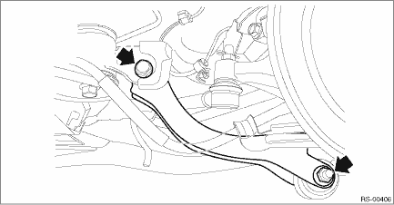
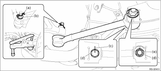
3. Remove the lateral link assembly - front.
(1) Remove the snap pin (a) and nut (b).
(2) Remove the ball joint from the housing assembly - rear axle.
Preparation tool:
Tie-rod ball joint puller
(3) Scribe alignment marks (c) on the adjusting bolt for lateral link assembly - front and on the rear sub frame assembly.
(4) Remove the adjusting bolt (d), and remove the lateral link assembly - front.
CAUTION:
When removing the adjusting bolt (d), make sure to fix the bolt head in place when loosening the nut (e).
 Assembly
REAR SUSPENSION > Front Lateral LinkASSEMBLY1. Before assembly, inspect the following items and replace any faulty part with a new one.• Visually check the lateral link assembly - front for d ...
 Disassembly
REAR SUSPENSION > Front Lateral LinkDISASSEMBLYUsing the ST, push out the bushing B - lateral link.Preparation tool:ST-A & ST-B: INSTALLER & REMOVER (20099AE000) ...
Other materials:
Removal
MECHANICAL(H4DO) > Cylinder HeadREMOVAL1. CYLINDER HEAD RH1. Remove the engine from the vehicle. Engine Assembly > REMOVAL">2. Remove the intake manifold. Intake Manifold > REMOVAL">3. Remove the engine wiring harness. Engine Wiring Harness > REMOVAL">4. Remove ...
Steering responsive fog lights warning indicator/ Steering responsive fog
lights OFF indicator (models with EyeSight system)
NOTE
For details about the steering responsive
fog lights system, refer to "Steering
responsive fog lights system (models
with EyeSight system)"
Steering responsive fog lights
warning indicator
This indicator appears when the steering
responsive fog lights system malfunctions.
When this ...
Installation
DRIVE SHAFT SYSTEM > Front Hub Unit BearingINSTALLATION1. Place the front brake back plate between the front axle housing and the front hub unit bearing, and tighten the bolt.CAUTION:• Do not get closer the tool which charged magnetism to magnetic encoder.• Be careful not to damage th ...
