Subaru Crosstrek Service Manual: Removal
POWER ASSISTED SYSTEM (POWER STEERING) > Electric Power Steering Gearbox
REMOVAL
CAUTION:
• The power steering control module continues to operate after the engine stops and calculate the temperature in the control module. Therefore, before starting service of the power steering system which requires disconnection of the connector, stop the engine and allow approx. 30 minutes until the control module becomes cold.
• Before removal or installation, be sure to remove any foreign matter (dust, moisture, oil, etc.) from the power steering control module connector.
1. Lift up the vehicle, and then remove the front wheels.
2. Remove the under cover - front. Front Under Cover > REMOVAL">
3. Remove the universal joint assembly - steering. Universal Joint > REMOVAL">
4. Disconnect the ground cable from battery. NOTE">
5. Adjust the tilt position of the column assembly - steering to the lowest position and lock the tilt lever.
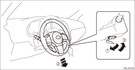
6. Remove the universal joint assembly - steering. Universal Joint > REMOVAL">
7. Disconnect the connector and harness clamp from power steering control module.
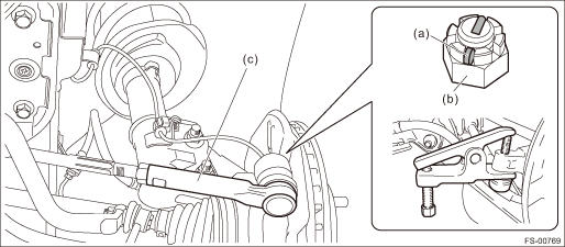
8. Disconnect the tie-rod end.
(1) Pull out the cotter pin (a).
(2) Remove the castle nut (b).
(3) Using a tie-rod ball joint puller, remove the tie-rod end (c).
Preparation tool:
Tie-rod ball joint puller
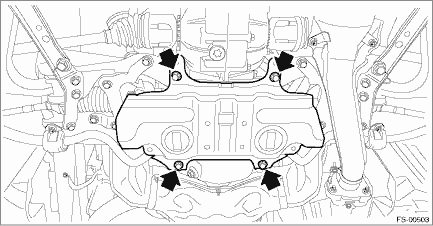
9. Remove the front crossmember support.
10. Remove the front exhaust pipe assembly. Front Exhaust Pipe > REMOVAL">
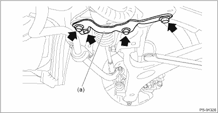
11. Remove the support plate - front crossmember (a).
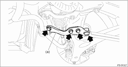
12. Remove the bolts securing the steering gearbox assembly, and remove the stiffener (a) and steering gearbox assembly.
 Adjustment
POWER ASSISTED SYSTEM (POWER STEERING) > Electric Power Steering GearboxADJUSTMENT1. GEARBOX BACKLASH ADJUSTMENT1. Remove the steering gearbox assembly. Electric Power Steering Gearbox > REMOVA ...
 Assembly
POWER ASSISTED SYSTEM (POWER STEERING) > Electric Power Steering GearboxASSEMBLY1. Install the tie-rod into rack.Tightening torque:90 N·m (9.18 kgf-m, 66.4 ft-lb)NOTE:Check the mating face o ...
Other materials:
Inspection
HVAC SYSTEM (HEATER, VENTILATOR AND A/C) > CompressorINSPECTION1. MAGNET CLUTCH CLEARANCE INSPECTION1. Check the clearance of entire circumference around the drive plate and pulley.Specification:0.3 — 0.6 mm (0.0118 — 0.0236 in)2. Replace the compressor assembly if the inspection result is no ...
Dtc p0138 o2 sensor circuit high voltage bank 1 sensor 2
ENGINE (DIAGNOSTICS)(H4DO) > Diagnostic Procedure with Diagnostic Trouble Code (DTC)DTC P0138 O2 SENSOR CIRCUIT HIGH VOLTAGE BANK 1 SENSOR 2DTC detecting condition:Detected when two consecutive driving cycles with fault occur.CAUTION:After servicing or replacing faulty parts, perform Clear Memory ...
Dtc b1837 short in curtain airbag lh squib circuit (to ground)
AIRBAG SYSTEM (DIAGNOSTICS) > Diagnostic Chart with Trouble CodeDTC B1837 SHORT IN CURTAIN AIRBAG LH SQUIB CIRCUIT (TO GROUND)Diagnosis start condition:Ignition voltage is 10 V to 16 V.DTC detecting condition:• Curtain airbag harness (LH) circuit is shorted to ground.• Curtain airbag ...
