Subaru Crosstrek Service Manual: Adjustment
POWER ASSISTED SYSTEM (POWER STEERING) > Electric Power Steering Gearbox
ADJUSTMENT
1. GEARBOX BACKLASH ADJUSTMENT
1. Remove the steering gearbox assembly. Electric Power Steering Gearbox > REMOVAL">
2. Loosen the lock nut and adjusting screw.
3. Apply a coat of grease to the sliding surface (B) of the pad - pressure (a) and seating surface (C) of spring - gearbox (b), and then insert the pad - pressure (a) into steering body.
4. Charge the adjusting screw (c) with grease (D), and then insert the spring - gearbox (b) into adjusting screw. Then install on the steering body.
Preparation items:
Grease: Multemp AC-P
5. Apply liquid gasket to 1/3 or more (A) of entire perimeter of adjusting screw thread (c).
Preparation items:
Liquid gasket: THREE BOND TB-1111B

6. Tighten the adjusting screw to 9.8 N·m (1.0 kgf-m, 7.2 ft-lb), then loosen it.
7. Tighten the adjusting screw to 6 N·m (0.6 kgf-m, 4.4 ft-lb).
8. Loosen the adjusting screw by 20°.
9. While fixing the adjusting screw, tighten the lock nuts.
Tightening torque:
49.4 N·m (5.04 kgf-m, 36.4 ft-lb)
2. FRONT WHEEL ALIGNMENT ADJUSTMENT
1. Adjust the front toe. Wheel Alignment > ADJUSTMENT">
2. Check the steering angle of the wheels.
Standard of steering angle:
Inner wheel | 38.2°±1.5° |
Outer wheel | 33.6°±1.5° |
3. When the steering wheel is in the following condition, perform the steering wheel installation over again.
• When wheels are set in the straight ahead position, the steering wheel spokes are not horizontal.
• Error is more than 5° on the periphery of the steering wheel.
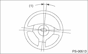
(1) | 5° or less |
4. If the steering wheel spokes are not horizontal with vehicle set in the straight ahead position after this adjustment, correct it by turning the right and left tie-rods in the opposite direction from each other by the same angle. Also check that there are no abnormal steering effort, failure of the steering wheel to return or other faults.
5. Adjust the steering angle sensor. (Models without EyeSight) VDC Control Module and Hydraulic Control Unit (VDCCM&H/U) > ADJUSTMENT">
6. Adjust the steering angle sensor. (Models with EyeSight)
• Neutral of Steering Angle Sensor & Lateral G Sensor 0 point setting VDC Control Module and Hydraulic Control Unit (VDCCM&H/U) > ADJUSTMENT">
• Longitudinal G sensor & lateral G sensor 0 point setting VDC Control Module and Hydraulic Control Unit (VDCCM&H/U) > ADJUSTMENT">

 Removal
POWER ASSISTED SYSTEM (POWER STEERING) > Electric Power Steering GearboxREMOVALCAUTION:• The power steering control module continues to operate after the engine stops and calculate the temper ...
Other materials:
Dtc p0751 shift solenoid "a" performance/stuck off
CONTINUOUSLY VARIABLE TRANSMISSION (DIAGNOSTICS) > Diagnostic Procedure with Diagnostic Trouble Code (DTC)DTC P0751 SHIFT SOLENOID "A" PERFORMANCE/STUCK OFFDTC detecting condition:Detected when two consecutive driving cycles with fault occur.Trouble symptom:• Shift control malfunc ...
Preparation tool
POWER ASSISTED SYSTEM (POWER STEERING) (DIAGNOSTICS) > General DescriptionPREPARATION TOOL1. SPECIAL TOOLILLUSTRATIONTOOL NUMBERDESCRIPTIONREMARKS — SUBARU SELECT MONITOR 4Used for setting of each function and troubleshooting for electrical system.NOTE:For detailed operation procedures of Subar ...
List
EyeSight (DIAGNOSTICS) > Diagnostic Code(s) DisplayLIST• List of Diagnostic Trouble Code (DTC)DTCItemContents of diagnosisReferenceU0073CONTROL MODULE COMMUNICATION BUS OFFDetected when bus off status (the stereo camera detects the failure and is disconnected from CAN line) occurs. Diagnost ...
