Subaru Crosstrek Service Manual: Assembly
POWER ASSISTED SYSTEM (POWER STEERING) > Electric Power Steering Gearbox
ASSEMBLY
1. Install the tie-rod into rack.
Tightening torque:
90 N·m (9.18 kgf-m, 66.4 ft-lb)
NOTE:
Check the mating face of rack and tie-rod for foreign matter such as dust etc.
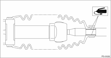
2. Apply a coat of grease to the tie-rod groove, and then install the boot - steering gearbox to the housing.
NOTE:
Make sure that the boot - steering gearbox is installed without unusual inflation or deflation.
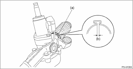
3. Using the boot clamp pliers, crimp the boot so that the clearance (b) of the band - boot (a) crimp portion becomes 2 mm (0.08 in) or less.
NOTE:
Use a new band - boot.
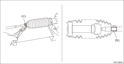
4. Fix the end of the boot - steering gearbox with clip - boot tie-rod (a).
5. After installation, check that the end of the boot - steering gearbox is installed to the groove (b) of the tie-rod.
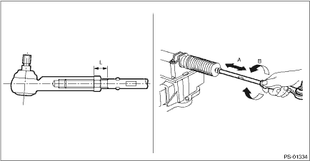
6. If the tie-rod end has been removed, screw in lock nut and tie-rod end to the threaded portion of tie-rod, and tighten the lock nut temporarily in a position as shown in the figure.
Installed tie-rod length L:
33 mm (1.3 in)
7. Inspect the steering gearbox assembly as follows:
(1) “A” Holding the tie-rod end, repeat lock to lock several times as quickly as possible.
(2) “B” Holding the tie-rod end, turn it slowly at a radius several times as large as possible.
(3) Finally, make sure that the boot - steering gearbox is installed in the specified position without inflating.
8. Remove the steering gearbox assembly from ST.
 Removal
POWER ASSISTED SYSTEM (POWER STEERING) > Electric Power Steering GearboxREMOVALCAUTION:• The power steering control module continues to operate after the engine stops and calculate the temper ...
 Disassembly
POWER ASSISTED SYSTEM (POWER STEERING) > Electric Power Steering GearboxDISASSEMBLYCAUTION:• Nut for fixing the rack is on the driver’s side only. When removing the tie-rod on the passe ...
Other materials:
Specification
VEHICLE DYNAMICS CONTROL (VDC) > ABS Sequence ControlSPECIFICATION1. CONDITIONS FOR COMPLETION OF ABS SEQUENCE CONTROLWhen the following conditions develop, the ABS sequence control stops and ABS operation is returned to the normal control mode.• When the speed of at least one wheel reaches ...
Seatbelt safety tips
WARNING
All persons in the vehicle should
fasten their seatbelts BEFORE
the vehicle starts to move. Otherwise,
the possibility of serious
injury becomes greater in the
event of a sudden stop or accident.
All belts should fit snugly in order
to provide full restraint. Loose
fittin ...
Dtc c2023 tire 3 air pressure low (normal mode)
TIRE PRESSURE MONITORING SYSTEM (DIAGNOSTICS) > Diagnostic Procedure with Diagnostic Trouble Code (DTC)DTC C2023 TIRE 3 AIR PRESSURE LOW (NORMAL MODE)NOTE:Refer to DTC C2024 for diagnostic procedure. Diagnostic Procedure with Diagnostic Trouble Code (DTC) > DTC C2024 TIRE 4 AIR PRESSURE LOW ( ...
