
Subaru Crosstrek Service Manual: Removal
LIGHTING SYSTEM > Headlight Bulb
REMOVAL
1. HIGH BEAM
CAUTION:
• Do not perform work with wet hands, because there is a possibility of electrical shock.
• Do not leave the light assembly - head without the bulb for a long time. Dust, moisture, etc. entering the light may affect its performance.
1. Disconnect the ground cable from battery. NOTE">
2. Remove the air intake duct. (When removing RH side) Air Intake Duct > REMOVAL">
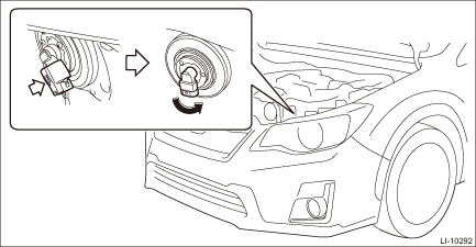
3. Disconnect the connector and remove the high beam bulb.
CAUTION:
Use a dry clean cloth so that no grease or water adheres to the glass portion of the bulb.
2. HALOGEN TYPE LOW BEAM
CAUTION:
• Do not perform work with wet hands, because there is a possibility of electrical shock.
• Do not leave the light assembly - head without the bulb for a long time. Dust, moisture, etc. entering the light may affect its performance.
1. Disconnect the ground cable from battery. NOTE">
2. Remove the air intake duct. (When removing RH side) Air Intake Duct > REMOVAL">
3. Turn the filler neck of the tank - washer front clockwise. (When removing LH side)
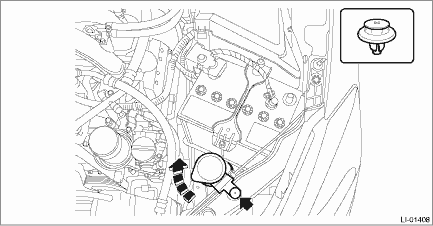
4. Disconnect the connector and remove the low beam bulb.
CAUTION:
• Make sure to check if any bulb O-ring is remained on the housing side as this may sometimes happen.
• Use a dry clean cloth so that no grease or water adheres to the glass portion of the bulb.
3. HID TYPE LOW BEAM
When removing RH side
CAUTION:
• Do not perform work with wet hands, because there is a possibility of electrical shock.
• Because the lighting circuit uses high voltage, be sure to confirm that the power supply is turned off before operation.
• Do not leave the light assembly - head without the bulb and cover - headlight for a long time. Dust, moisture, etc. entering the light may affect its performance.
1. Disconnect the ground cable from battery. NOTE">
2. Remove the air intake duct. Air Intake Duct > REMOVAL">
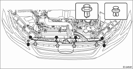
3. Remove the clip, and remove the bracket - grille.
CAUTION:
To prevent damage to the bracket - grille, make sure to remove all clips.
4. Remove the bumper face - front. Front Bumper > REMOVAL">
5. Remove the light assembly - head. Headlight Assembly > REMOVAL">
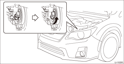
6. Remove the low beam bulb.
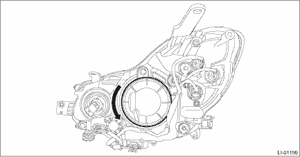
(1) Remove the cover - headlight.
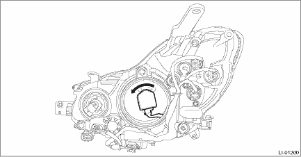
(2) Remove the bulb socket.
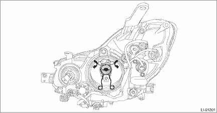
(3) Unlock the bulb spring, and remove the low beam bulb.
CAUTION:
Use a dry clean cloth so that no grease or water adheres to the glass portion of the bulb.
When removing LH side
CAUTION:
• Do not perform work with wet hands, because there is a possibility of electrical shock.
• Because the lighting circuit uses high voltage, be sure to confirm that the power supply is turned off before operation.
• Do not leave the light assembly - head without the bulb and cover - headlight for a long time. Dust, moisture, etc. entering the light may affect its performance.
1. Remove the battery. Battery > REMOVAL">
2. Remove the low beam bulb.
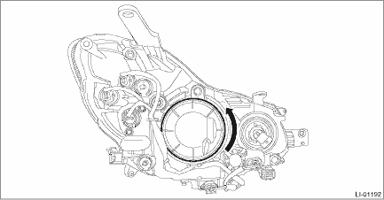
(1) Remove the cover - headlight.
(2) Remove the bulb socket.
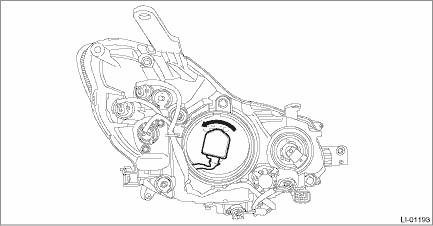
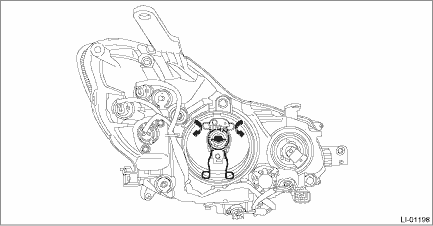
(3) Unlock the bulb spring, and remove the low beam bulb.
CAUTION:
Use a dry clean cloth so that no grease or water adheres to the glass portion of the bulb.
 Inspection
LIGHTING SYSTEM > Headlight BulbINSPECTION1. HALOGEN TYPECAUTION:• Do not perform work with wet hands, because there is a possibility of electrical shock.• Do not leave the light assemb ...
 Installation
LIGHTING SYSTEM > Headlight BulbINSTALLATIONCAUTION:Install so that the front end of the under cover (b) comes inside the bumper face - front (a), and the front end of the mud guard (c) comes outsi ...
Other materials:
Windshield wiper blade rubber
1) Metal support
1. Grasp the locked end of the blade
rubber assembly and pull it firmly until the
stoppers on the rubber are free of the
metal support.
1) Metal spines
2. If the new blade rubber is not provided
with two metal spines, remove the metal
spines from the old blade rubber ...
AUX
WARNING
Do not operate the player's controls
or connect the portable audio device
while driving. Doing so may result in
loss of control of your vehicle and
cause an accident or serious injury.
CAUTION
Do not leave portable audio device
in the vehicle. The temperature
inside the vehicle ...
Dtc p0345 camshaft position sensor "a" circuit bank 2
ENGINE (DIAGNOSTICS)(H4DO) > Diagnostic Procedure with Diagnostic Trouble Code (DTC)DTC P0345 CAMSHAFT POSITION SENSOR "A" CIRCUIT BANK 2DTC DETECTING CONDITION:Immediately at fault recognitionTROUBLE SYMPTOM:• Engine stall• Failure of engine to startCAUTION:After servicing ...
