
Subaru Crosstrek Service Manual: Dtc p0345 camshaft position sensor "a" circuit bank 2
ENGINE (DIAGNOSTICS)(H4DO) > Diagnostic Procedure with Diagnostic Trouble Code (DTC)
DTC P0345 CAMSHAFT POSITION SENSOR "A" CIRCUIT BANK 2
DTC DETECTING CONDITION:
Immediately at fault recognition
TROUBLE SYMPTOM:
• Engine stall
• Failure of engine to start
CAUTION:
After servicing or replacing faulty parts, perform Clear Memory Mode Clear Memory Mode > OPERATION"> , and Inspection Mode Inspection Mode > PROCEDURE">.
WIRING DIAGRAM:
Engine electrical system Engine Electrical System">
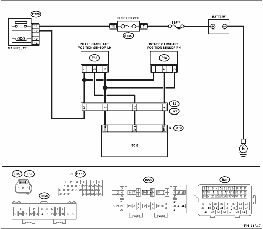
| STEP | CHECK | YES | NO |
1.CHECK POWER SUPPLY OF CAMSHAFT POSITION SENSOR.
1) Turn the ignition switch to OFF.
2) Disconnect the connector from camshaft position sensor.
3) Turn the ignition switch to ON.
4) Measure the voltage between camshaft position sensor connector and engine ground.
Connector & terminal
(E35) No. 1 (+) — Engine ground (−):
Is the voltage 10 V or more?
Diagnostic Procedure with Diagnostic Trouble Code (DTC) > DTC P0345 CAMSHAFT POSITION SENSOR "A" CIRCUIT BANK 2">Go to Step 2.
Repair the harness and connector.
NOTE:
In this case, repair the following item:
• Open circuit or short circuit to ground in harness between main relay connector and camshaft position sensor connector
• Poor contact of coupling connector
2.CHECK HARNESS BETWEEN ECM AND CAMSHAFT POSITION SENSOR CONNECTOR.
1) Turn the ignition switch to OFF.
2) Disconnect the connector from ECM.
3) Measure the resistance between ECM connector and camshaft position sensor connector.
Connector & terminal
(B136) No. 15 — (E35) No. 2:
(B136) No. 34 — (E35) No. 3:
Is the resistance less than 1 ??
Diagnostic Procedure with Diagnostic Trouble Code (DTC) > DTC P0345 CAMSHAFT POSITION SENSOR "A" CIRCUIT BANK 2">Go to Step 3.
Repair the harness and connector.
NOTE:
In this case, repair the following item:
• Open circuit in harness between ECM connector and camshaft position sensor connector
• Poor contact of coupling connector
3.CHECK HARNESS BETWEEN ECM AND CAMSHAFT POSITION SENSOR CONNECTOR.
Measure the resistance between camshaft position sensor connector and engine ground.
Connector & terminal
(E35) No. 2 — Engine ground:
Is the resistance 1 M? or more?
Diagnostic Procedure with Diagnostic Trouble Code (DTC) > DTC P0345 CAMSHAFT POSITION SENSOR "A" CIRCUIT BANK 2">Go to Step 4.
Repair short circuit to ground in harness between ECM connector and camshaft position sensor connector.
4.CHECK HARNESS BETWEEN ECM AND CAMSHAFT POSITION SENSOR CONNECTOR.
Measure the voltage between camshaft position sensor connector and engine ground.
Connector & terminal
(E35) No. 2 (+) — Engine ground (−):
Is the voltage 5 V or more?
Repair the short circuit to power in the harness between ECM connector and camshaft position sensor connector.
Diagnostic Procedure with Diagnostic Trouble Code (DTC) > DTC P0345 CAMSHAFT POSITION SENSOR "A" CIRCUIT BANK 2">Go to Step 5.
5.CHECK CONDITION OF CAMSHAFT POSITION SENSOR.
Is the camshaft position sensor installation bolt tightened securely?
Diagnostic Procedure with Diagnostic Trouble Code (DTC) > DTC P0345 CAMSHAFT POSITION SENSOR "A" CIRCUIT BANK 2">Go to Step 6.
Tighten the camshaft position sensor installation bolt securely.
6.CHECK CAMSHAFT POSITION SENSOR.
Check the waveform of the camshaft position sensor. Engine Control Module (ECM) I/O Signal">
Is there any abnormality in waveform?
Replace the camshaft position sensor. Camshaft Position Sensor">
Repair the following item.
• Poor contact of ECM connector
• Poor contact of camshaft position sensor connector
• Poor contact of coupling connector
1. OUTLINE OF DIAGNOSIS
NOTE:
For the detection standard, refer to DTC P0340. Diagnostic Procedure with Diagnostic Trouble Code (DTC) > DTC P0340 CAMSHAFT POSITION SENSOR "A" CIRCUIT BANK 1 OR SINGLE SENSOR">
 Dtc p0341 camshaft position sensor "a" circuit range/performance bank 1 or single sensor
ENGINE (DIAGNOSTICS)(H4DO) > Diagnostic Procedure with Diagnostic Trouble Code (DTC)DTC P0341 CAMSHAFT POSITION SENSOR "A" CIRCUIT RANGE/PERFORMANCE BANK 1 OR SINGLE SENSORNOTE:For the di ...
 Dtc p0346 camshaft position sensor "a" circuit range/performance bank 2
ENGINE (DIAGNOSTICS)(H4DO) > Diagnostic Procedure with Diagnostic Trouble Code (DTC)DTC P0346 CAMSHAFT POSITION SENSOR "A" CIRCUIT RANGE/PERFORMANCE BANK 2NOTE:For the diagnostic procedur ...
Other materials:
Dtc p1451 evap system clog detected (pipe)
ENGINE (DIAGNOSTICS)(H4DO) > Diagnostic Procedure with Diagnostic Trouble Code (DTC)DTC P1451 EVAP SYSTEM CLOG DETECTED (PIPE)DTC DETECTING CONDITION:Detected when two consecutive driving cycles with fault occur.CAUTION:After servicing or replacing faulty parts, perform Clear Memory Mode Clear M ...
Operation
SECURITY AND LOCKS > Function Setting (Customize)OPERATIONDisabling/Activating the keyless access systemThe following functions are disabled when the keyless access system functions are disabled:• LOCK function performed by the operation of touch sensor on the door outer handle• Rear ...
Dtc c0073 abnormal lateral g sensor output
VEHICLE DYNAMICS CONTROL (VDC) (DIAGNOSTICS) > Diagnostic Procedure with Diagnostic Trouble Code (DTC)DTC C0073 ABNORMAL LATERAL G SENSOR OUTPUTDTC detecting condition:Defective lateral G sensorTrouble symptom:• VDC does not operate.• EyeSight does not operate.STEPCHECKYESNO1.CHECK IN ...
