Subaru Crosstrek Service Manual: Removal
EyeSight > Stereo Camera
REMOVAL
CAUTION:
• When the stereo camera or windshield glass has been replaced, removed or installed, always perform the adjustment and inspection of the camera. (When the stereo camera has been replaced with a new part, the camera remains in a failed state until adjustment and inspection are performed.)
• Since the stereo camera is a precision equipment, install the protective cover before handling it. (New stereo camera is equipped with a protective cover as a service part.)
• During removal, do not hold at the left and right cameras.
• Do not apply any impact to the stereo camera. (Even the slightest shock will deviate the optical axis of the camera, resulting in the loss of normal operation of the camera.)
• Do not disassemble the stereo camera.
• Attach the protective cover to the replacement part, put it into the box in the same way as the other parts and return it. Cover the replaced stereo camera with a protective cover.
• Do not touch the lens filter on the stereo camera. If touched, replace the stereo camera.
• When removing the stereo camera cover assembly, cover with dust-free paper such as copy paper to avoid interference with the lens filter section, and attach the paper using tape while being careful not to let the adhesive surface contact the glass surface. Be sure to remove the paper after the procedure.
Also, do not put your hand on the polyurethane section of the windshield contact surface. Doing so may cause the polyurethane section to be removed, which may interfere with the normal operation if it hangs down in front of the lens filter section.
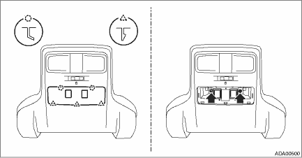
1. Disconnect the ground cable from battery. NOTE">
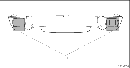
2. Attach dust-free paper (a) such as copy paper to the stereo camera cover assembly.
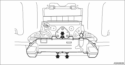
3. Remove the stereo camera cover assembly.
(1) Disconnect the claws and hooks and remove the cap.
(2) Remove the bolt.
(3) Pull down the rear of the stereo camera cover assembly, and then release the clips.
(4) Release the hook on the front side of stereo camera cover assembly.
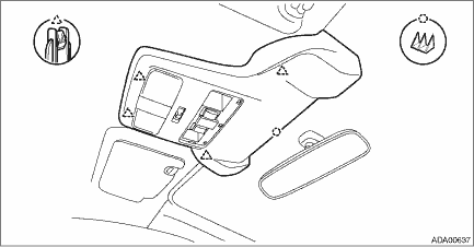
(5) Disconnect the connectors, and remove the stereo camera cover assembly.
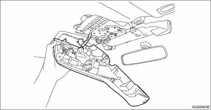
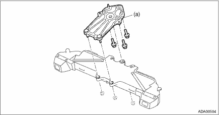
4. Remove the stereo camera.
(1) Disconnect the connector.
(2) Remove the nuts, and then remove the stereo camera.
NOTE:
Remove the camera plate (a) as required.
 Installation
EyeSight > Stereo CameraINSTALLATIONCAUTION:• Do not remove the protective cover until just before installing the stereo camera cover assembly. Using the bolt and nut, install the stereo came ...

Other materials:
Dtc b1409 scu communication
IMMOBILIZER (DIAGNOSTICS) > Diagnostic Procedure with Diagnostic Trouble Code (DTC)DTC B1409 SCU COMMUNICATIONDTC detecting condition:Communication failure between body integrated unit and security control moduleCAUTION:When the body integrated unit is replaced, registration of the immobilizer sy ...
Unit settings
Sound quality adjustment, screen adjustment,
and information of the audio unit are
displayed.
1. Press the HOME button on the audio
panel.
2. Touch the "SETTINGS" key.
3. Select the items to be set.
Available setting:
General settings: Select the
tab to
check the system ...
Assembly
SEATS > Rear SeatASSEMBLYCAUTION:• Do not reuse hog rings.• Secure the hog ring using hog ring pliers.• Install the hog rings to the specified points securely and make sure that there is no wrinkle or twisting on the cover COMPL - rear backrest.1. Assemble the cover COMPL - rear ...
