Subaru Crosstrek Service Manual: Removal
EMISSION CONTROL (AUX. EMISSION CONTROL DEVICES)(H4DO) > EGR Cooler
REMOVAL
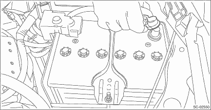
1. Disconnect the ground cable from battery.
2. Drain engine coolant. Engine Coolant > REPLACEMENT">
3. Remove the center exhaust pipe. Center Exhaust Pipe > REMOVAL">
4. Lower the vehicle.
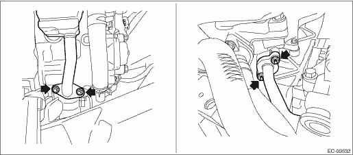
5. Remove the clip (A), and loosen the clamps (B) and (C) securing the air intake boot.
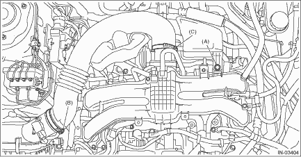
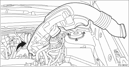
6. Remove the air intake boot from the air cleaner case (rear) and throttle body, and move the air intake boot aside so that it does not interfere with the work.
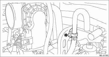
7. Remove the clip holding the air breather hose to the engine rear hanger. (MT model)
8. Disconnect the engine harness connector.
(1) Remove the bolt (A) securing the bulkhead harness connector bracket.
(2) Disconnect the bulkhead harness connector from the engine harness connector (black) and engine harness connector (brown).
9. Remove the engine rear hanger.
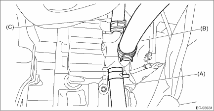
10. Disconnect the engine coolant hose (A), engine coolant hose (B) (CVT model) and engine coolant hose (C) from the EGR cooler.
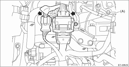
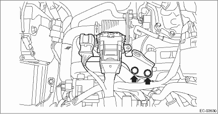
11. Remove the nuts which secure the EGR cooler to the cylinder head RH.
12. Remove the nuts which secure the EGR cooler to the EGR control valve.
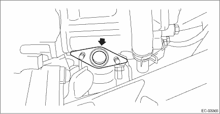
13. Remove the gasket from the stud bolt.
 Inspection
EMISSION CONTROL (AUX. EMISSION CONTROL DEVICES)(H4DO) > EGR CoolerINSPECTION1. Check that the EGR cooler has no deformation, cracks or other damages.2. Check that the hose has no cracks, damage or ...
 Installation
EMISSION CONTROL (AUX. EMISSION CONTROL DEVICES)(H4DO) > EGR CoolerINSTALLATION1. Set the gasket to the stud bolt.NOTE:Use a new gasket.2. Temporarily tighten the bolts securing the EGR cooler to t ...
Other materials:
Removal
HVAC SYSTEM (HEATER, VENTILATOR AND A/C) > Heater Vent DuctREMOVALCAUTION:Before handling the airbag system components, refer to “CAUTION” of “General Description” in “AIRBAG SYSTEM”. General Description > CAUTION">1. Disconnect the battery ground c ...
Dtc u0422 invalid data received from body control module
KEYLESS ACCESS WITH PUSH BUTTON START SYSTEM (DIAGNOSTICS) > Diagnostic Procedure with Diagnostic Trouble Code (DTC)DTC U0422 INVALID DATA RECEIVED FROM BODY CONTROL MODULEDetected when CAN data from BIU is abnormal.NOTE:Perform the diagnosis for LAN system. Basic Diagnostic Procedure > PROCE ...
Coat hook
The Subaru Ascent includes a coat hook integrated into the rear passenger assist
grip, offering a practical place to hang clothing items.
WARNING
Follow these safety guidelines when using the coat hook in the Subaru Ascent.
Do not use rigid or pointed hangers. Always hang garments di ...
